
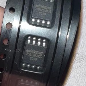
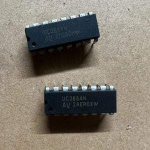
The NC7SZ11P6X from onsemi (formerly Fairchild) is a single 3-input AND gate from the Ultra High Speed (UHS) TinyLogic family in a 6-pin SC-70-6 (SOT-363) package (2.0 x 1.25 mm). It operates from 1.65 V to 5.5 V with 2-µA max quiescent current. Key specs include 2.7-ns propagation delay at 5 V (typical), 7.5-ns max at 5 V with 50-pF load, ±32-mA output drive at 5 V, and over-voltage tolerant inputs up to 7 V independent of VCC. The output is high-impedance when VCC is 0 V. Features patented noise/EMI reduction circuitry. Operating temperature range is -40°C to +85°C.
Home » Integrated Circuits ICs, Logic Chips » NC7SZ11P6X
NC7SZ11P6X
3-input AND gate, 1.65-5.5V, 2.7ns tpd@5V, ±32mA drive, 7V-tolerant inputs, SC-70-6, -40~85°C
2290
Effective Inventory
Manufacturer Part:
NC7SZ11P6X
Package:
SC-70-6 / SOT-363 / SC-88 (2.0 x 1.25 x 1.0 mm, 0.65mm pitch)
Brand:
Product Categories:
Quality Commitment
Shipping & Payment
Service & Packaging
Product Manual
Other recommendations you may be interested in.
Description
Product Introduction: NC7SZ11P6X Product Introduction
The NC7SZ11P6X is a single 3-input AND gate from onsemi’s TinyLogic UHS (Ultra High Speed) family, originally designed by Fairchild Semiconductor before its acquisition by onsemi. The device is fabricated with advanced CMOS technology to achieve high speed with high output drive while maintaining low static power dissipation across the 1.65-V to 5.5-V operating range.
The 3-input AND function computes Y = A AND B AND C. The output goes high only when all three inputs are high. This is useful for multi-condition enable circuits, address decoding, and fault detection where three independent conditions must all be satisfied before an action is taken.
The 2.7-ns typical propagation delay at 5 V (7.5-ns max with 50-pF load) makes the NC7SZ11 suitable for high-speed digital logic. The ±32-mA output drive at 5 V can directly drive LEDs, relay coils, and multiple TTL/CMOS inputs without a buffer.
The inputs tolerate voltages up to 7 V independently of VCC, enabling the device to accept 5-V signals even when operating at 1.8-V VCC. This is valuable for voltage translation — a 5-V input signal is correctly recognized as a logic high even when the gate is powered from 1.8 V, and the 1.8-V output is compatible with downstream 1.8-V logic.
When VCC is 0 V, the inputs and output are high-impedance, preventing backflow current in partially-powered systems. The 2-µA maximum quiescent current makes the device suitable for always-on logic.
The SC-70-6 (SOT-363) package occupies only 2.5 mm² of board area — one of the smallest logic gate packages available. This makes the NC7SZ11 ideal for adding glue logic in space-constrained designs where a full PLD or CPLD would be overkill.
The P6X suffix denotes SC-70-6 tape-and-reel packaging. Other package options include P5X (SOT-23-5) and M5X (MicroPak-5).
Working Principle: NC7SZ11P6X Working Principle
**CMOS AND Gate Logic:** The NC7SZ11 implements the Boolean AND function (Y = A · B · C) using complementary CMOS transistors. The input stage consists of three series-connected NMOS transistors and three parallel-connected PMOS transistors. When all three inputs are high, all three NMOS transistors conduct (creating a path from output to ground through the series chain), and all three PMOS transistors are off. When any input is low, the corresponding NMOS transistor turns off (breaking the series chain) and the corresponding PMOS transistor turns on (creating a path from VCC to output).
**Over-Voltage Tolerant Inputs:** The input structures use a special circuit that allows input voltages to exceed VCC up to 7 V. This is achieved by isolating the input protection diodes from the VCC rail and using a floating n-well structure. When an input exceeds VCC, the parasitic diode to VCC is reverse-biased, preventing current flow into VCC.
**Power-Off High-Impedance:** When VCC = 0 V, an internal circuit disables the output driver, placing the output in a high-impedance state. This prevents the device from sourcing or sinking current when unpowered, which is critical in hot-swap and multi-voltage systems.
**EMI Reduction:** The patented noise/EMI reduction circuitry slows the output edge rate slightly (controlled slew rate) to reduce high-frequency spectral content that causes electromagnetic interference, while maintaining acceptable propagation delay.
Pin Description: NC7SZ11P6X Pin Definition and Functions
| Pin | Name | Type | Description |
|---|---|---|---|
| 1 | Input A | I | AND gate input A; 7V tolerant; CMOS input with ~1pF capacitance; must not be left floating |
| 2 | Input B | I | AND gate input B; same characteristics as Input A |
| 3 | GND | G | Ground; connect to PCB ground plane |
| 4 | Input C | I | AND gate input C; same characteristics as Input A |
| 5 | Output Y | O | AND gate output; Y = A · B · C; push-pull; ±32mA at 5V; high-impedance when VCC=0V; controlled slew rate for EMI reduction |
| 6 | VCC | P | Supply voltage; 1.65V to 5.5V; bypass with 0.1µF ceramic to GND |
Application Scenarios: In which products and applications is NC7SZ11P6X used
| Application | Description |
|---|---|
| Multi-Condition Enable Gate | Combine three enable signals (power-good, temperature-ok, software-enable) into a single enable output; all three must be high to enable downstream circuit; Y = PWR_OK AND TEMP_OK AND SW_EN; replaces 2 two-input AND gates and saves board space |
| Address Decode Strobe | Generate chip-select from three address lines; Y = A15 AND A14 AND A13 produces a single strobe when all three address lines are high; 2.7ns propagation delay meets fast bus timing; ±32mA output drives multiple loads |
| Voltage Translation AND | Accept 5V input signals with 1.8V VCC; 7V-tolerant inputs correctly recognize 5V logic levels; 1.8V output compatible with low-voltage downstream logic; single gate replaces level translator + AND gate |
Alternative Models: What chips are recommended as replacements for NC7SZ11P6X
| Model | Manufacturer | Compatibility | Key Difference |
|---|---|---|---|
| NC7SZ11P5X | onsemi | Package Variant | Same 3-input AND gate in SOT-23-5 package; larger footprint but easier hand-soldering; pinout differs from SC-70-6 |
| SN74LVC1G11DCKR | TI | Functional Equivalent | 3-input AND gate; 1.65-5.5V; SC-70-6; 3.3ns tpd@5V; 24mA drive; use as TI-sourced alternative |
| 74AHC1G11GW | Nexperia | Functional Equivalent | 3-input AND gate; 2.0-5.5V; SOT-353; AHC family; slightly higher drive; use as Nexperia-sourced alternative |
| NC7SZ08P6X | onsemi | Family Variant (2-input AND) | 2-input AND gate; same SC-70-6 package; UHS TinyLogic family; use when only 2 inputs needed |
Recommend Parts
RK73H1ETTP20R0F
20Ohm +/-1% 0.063W thick film resistor, 0402, +/-100 ppm/C, AEC-Q200
Brand: KOA Speer
Package: 0402 (1005 Metric) 1.0 x 0.5 x 0.35 mm
IN STOCK: 33180pcs
Cargo cycle: 3-7 Days
The minimum order is 1
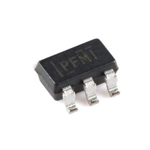
TPS77001DBVR
50mA LDO, adjustable 1.2-5.5V out, 35mV dropout, 17µA IQ, SOT-23-5
Brand: TI
Package: SOT-23-5 (2.9 x 1.6 x 1.45 mm)
IN STOCK: 5000pcs
Cargo cycle: 3-7 Days
The minimum order is 1
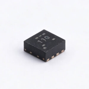
TPS61021ADSGR
3A synchronous boost converter, 1.8-5.5V, VSSOP-8
Brand: TI
Package: VSSOP-8 (3.0 x 3.0 mm, DSG package)
IN STOCK: 12398pcs
Cargo cycle: 3-7 Days
The minimum order is 1
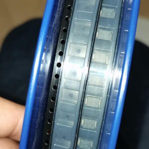
S1MB-13-F
1A 1000V GPP rectifier, 1.1V VF, 3μs trr, SMB/DO-214AA, -65~150°C
Brand: Diodes Inc
Package: SMB / DO-214AA (4.57 x 3.94 x 2.50mm)
IN STOCK: 3679pcs
Cargo cycle: 3-7 Days
The minimum order is 1
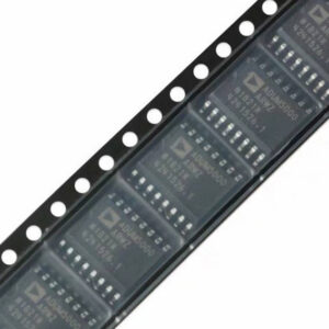
ADUM5000ARWZ-RL
500mW isolated DC-DC converter, 3.3/5V, SOIC-16W
Brand: ADI
Package: SOIC-16W (10.3 x 7.5 mm, RW package)
IN STOCK: 6373pcs
Cargo cycle: 3-7 Days
The minimum order is 1
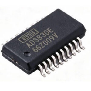
IN STOCK: 9357pcs
Cargo cycle: 3-7 Days
The minimum order is 1