Opens in a new tab

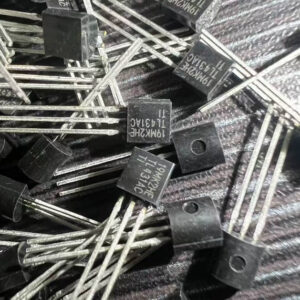
SN74LS125N

Quad non-inverting bus buffer, 3-state, active-LOW enable, LS TTL, PDIP-14

5000

Effective Inventory

Image for reference only

Manufacturer Part:

SN74LS125N

Package:

PDIP-14 (19.3 x 6.35 x 4.57mm, 2.54mm pitch, through-hole)

Brand:

Quality Commitment

Shipping & Payment

Service & Packaging

Product Manual

Other recommendations you may be interested in.

Description

Product Overview

The SN74LS125N from Texas Instruments contains four independent bus buffer gates with 3-state outputs controlled by active-LOW enables — essential for sharing a common data bus among multiple sources in a 14-pin PDIP package.

Key Specifications

Function Quad bus buffer with 3-state outputs
Logic Family LS (Low-power Schottky)
Supply Voltage 4.75V to 5.25V
Buffers 4 (independent, non-inverting)
Output Enable Active-LOW (OĒ, per buffer)
Output Type 3-state (HIGH, LOW, or high-impedance)
Propagation Delay 8-13ns typical
Output Drive IOL = 24mA, IOH = -2.6mA
Operating Temperature 0°C to +70°C
Package PDIP-14 (19.3 x 6.35mm)

Features

  • Four non-inverting buffers with 3-state outputs
  • Active-LOW output enable per buffer
  • High-impedance output when disabled
  • 24mA sink current for bus driving
  • Diode-clamped inputs

Applications

  • Bus buffer / driver
  • I/O port isolation
  • Multi-source data bus sharing
  • Level translation (5V to 3.3V with pull-ups)
Product Introduction: SN74LS125N Product Introduction

The SN74LS125N from Texas Instruments contains four independent non-inverting buffer gates with 3-state (tri-state) outputs. Each buffer has a data input (A), a data output (Y), and an active-LOW output enable (OĒ). When OĒ is LOW, Y = A (the buffer drives the bus). When OĒ is HIGH, Y enters a high-impedance state (electrically disconnected from the bus). The 3-state output is the key feature: multiple 74125 buffers (or other 3-state devices) can share a common bus, and only one drives the bus at a time while all others are in high-Z. The 24mA sink current provides strong bus driving capability. The non-inverting function means the output is the same polarity as the input. The 74125 is the complement of the 74126 (which has active-HIGH enables). For bus applications: multiple data sources connect through 74125 buffers to a common bus; a decoder selects which buffer is enabled (only one at a time); the selected source drives the bus. The N suffix denotes the PDIP-14 through-hole package.

Working Principle: SN74LS125N Working Principle

Each buffer in the SN74LS125N operates as a non-inverting pass gate with 3-state control. When OĒ (output enable) is LOW: Y = A; the buffer actively drives the bus line HIGH or LOW. When OĒ is HIGH: Y enters high-impedance (high-Z) state; the output is effectively disconnected from the bus; the bus line is free to be driven by another device. The 3-state output behaves like a switch: enabled = switch closed (Y follows A); disabled = switch open (Y floats). Only one 3-state device should drive a given bus line at any time; if two devices drive conflicting logic levels, bus contention occurs (excessive current flow, potential damage). A decoder or logic ensures exactly one enable is active at a time. The high-Z state is NOT the same as a HIGH logic level — it’s a floating state. Pull-up or pull-down resistors are often used on 3-state buses to define a known logic level when no device is driving. The 24mA sink capability allows the 74125 to drive heavily loaded bus lines.

Pin Description: SN74LS125N Pin Definition and Functions
Pin Name Type Description
1 1OĒ Input Buffer 1 output enable (active LOW)
2 1A Input Buffer 1 data input
3 1Y Output Buffer 1 output (3-state)
4 2OĒ Input Buffer 2 output enable (active LOW)
5 2A Input Buffer 2 data input
6 2Y Output Buffer 2 output (3-state)
7 GND Power Ground
8 3Y Output Buffer 3 output (3-state)
9 3A Input Buffer 3 data input
10 3OĒ Input Buffer 3 output enable (active LOW)
11 4Y Output Buffer 4 output (3-state)
12 4A Input Buffer 4 data input
13 4OĒ Input Buffer 4 output enable (active LOW)
14 VCC Power Supply (5V)
Application Scenarios: In which products and applications is SN74LS125N used
  • 4-Source Bus: 4 data sources → 1A-4A; decoder drives 1OĒ-4OĒ (one LOW at a time); all Y outputs on shared bus; selected source drives bus
  • Bi-Directional Bus: 74125 for output direction + 74125 for input direction; direction signal selects which buffer group is active
  • I/O Isolation: MCU I/O pin → A; OĒ from direction control; Y → peripheral bus; disconnect MCU from bus when not communicating
  • Level Translation: 3.3V signal → A (with current-limit resistor); 5V bus on Y; OĒ = LOW; 74125 safely passes 3.3V as valid TTL HIGH
Alternative Models: What chips are recommended as replacements for SN74LS125N
Model Manufacturer Key Difference Package Supply
74LS125N TI/Nexperia Original TTL version with 5V-only supply, typical propagation delay 10-15ns DIP-14 5V TTL
74LS125D TI/Nexperia Surface-mount SOIC version of LS with identical logic function SOIC-14 5V TTL
74HC125D TI/Nexperia CMOS version with wide 2-6V supply range, lower power consumption and higher noise immunity SOIC-14 2-6V CMOS
74HC125N TI/Nexperia Through-hole DIP version of HC family for prototyping and repair DIP-14 2-6V CMOS
74HCT125D TI/Nexperia CMOS with TTL-compatible input levels, ideal for mixing with LS devices at 5V SOIC-14 4.5-5.5V TTL-in
74HCT125N TI/Nexperia Through-hole DIP version of HCT family for prototyping and repair DIP-14 4.5-5.5V TTL-in
74LVC125D TI/Nexperia Low-voltage CMOS for 1.65-3.6V modern logic with 24mA output drive and bus-hold inputs SOIC-14 1.65-3.6V CMOS
74LVC125N TI/Nexperia Through-hole DIP version of LVC family for prototyping and repair DIP-14 1.65-3.6V CMOS

The 74125 is a Quad Bus Buffer with 3-State Output (Active-Low Enable). Family variants span from the original LS TTL (5V only) to modern LVC/AUP (down to 0.8V). HC and HCT versions offer 2-6V CMOS operation with HCT providing TTL-compatible input thresholds for mixed 5V systems. CD4000-series equivalents offer the widest 3-18V supply range at the cost of lower switching speed. DIP packages (N suffix) are through-hole; SOIC (D suffix) and TSSOP are surface-mount.

Recommend Parts

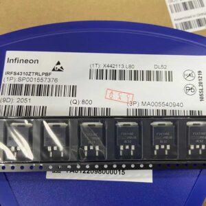
IRFS4310ZTRLPBF

IRFS4310ZTRLPBF – 100V N-Channel HEXFET Power MOSFET, 7 mΩ RDS(on), D2PAK (TO-263AB)

Brand: infineon

Package: D2PAK (TO-263AB)

IN STOCK: 11137pcs

Cargo cycle: 3-7 Days

The minimum order is 1

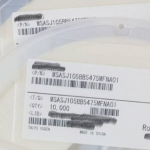
MSASJ105BB5475MFNA01

4.7uF 6.3V X5R MLCC, 0402, Taiyo Yuden

Brand: gigadevice

Package: 0402 (1005 Metric, 1.0 x 0.5 x 0.5 mm)

IN STOCK: 9701pcs

Cargo cycle: 3-7 Days

The minimum order is 1

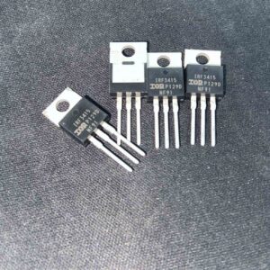
IRF3415PBF

150V N-channel power MOSFET, 43A, 41mΩ RDS(on), TO-220AB package

Brand: infineon

Package: TO-220AB

IN STOCK: 2940pcs

Cargo cycle: 3-7 Days

The minimum order is 1

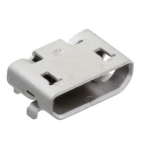
105017-1001

USB Type-C receptacle connector, 24-pin, SMD

Brand: Amphenol

Package: SMD (8.9 x 7.3 x 3.2 mm, right angle)

IN STOCK: 5335pcs

Cargo cycle: 3-7 Days

The minimum order is 1

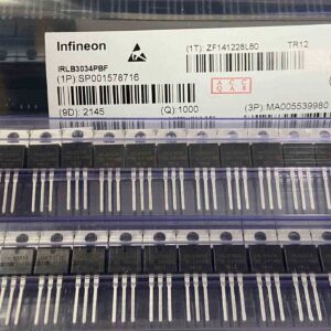
IRLB3034PBF

IRLB3034PBF – 40V N-Channel StrongIRFET Power MOSFET (Logic Level), 1.7 mΩ (max) @ 10V; 2.0 mΩ @ 4.5V RDS(on), TO-220AB

Brand: infineon

Package: TO-220AB

IN STOCK: 9724pcs

Cargo cycle: 3-7 Days

The minimum order is 1

XC6SLX75-2FGG484I

Spartan-6 LX75 FPGA, 74637 logic cells, 132 DSP, 3096KB BRAM, 408 I/O, FBGA-484 23x23mm, -2 speed, industrial -40~100C, AMD Xilinx

Brand: xilinx

Package: FGG484 (484-ball fine-pitch BGA, 23x23mm body, 1.0mm ball pitch, 22×22 ball array, 6 I/O banks, lead-free)

IN STOCK: 890pcs

Cargo cycle: 3-7 Days

The minimum order is 1