Opens in a new tab

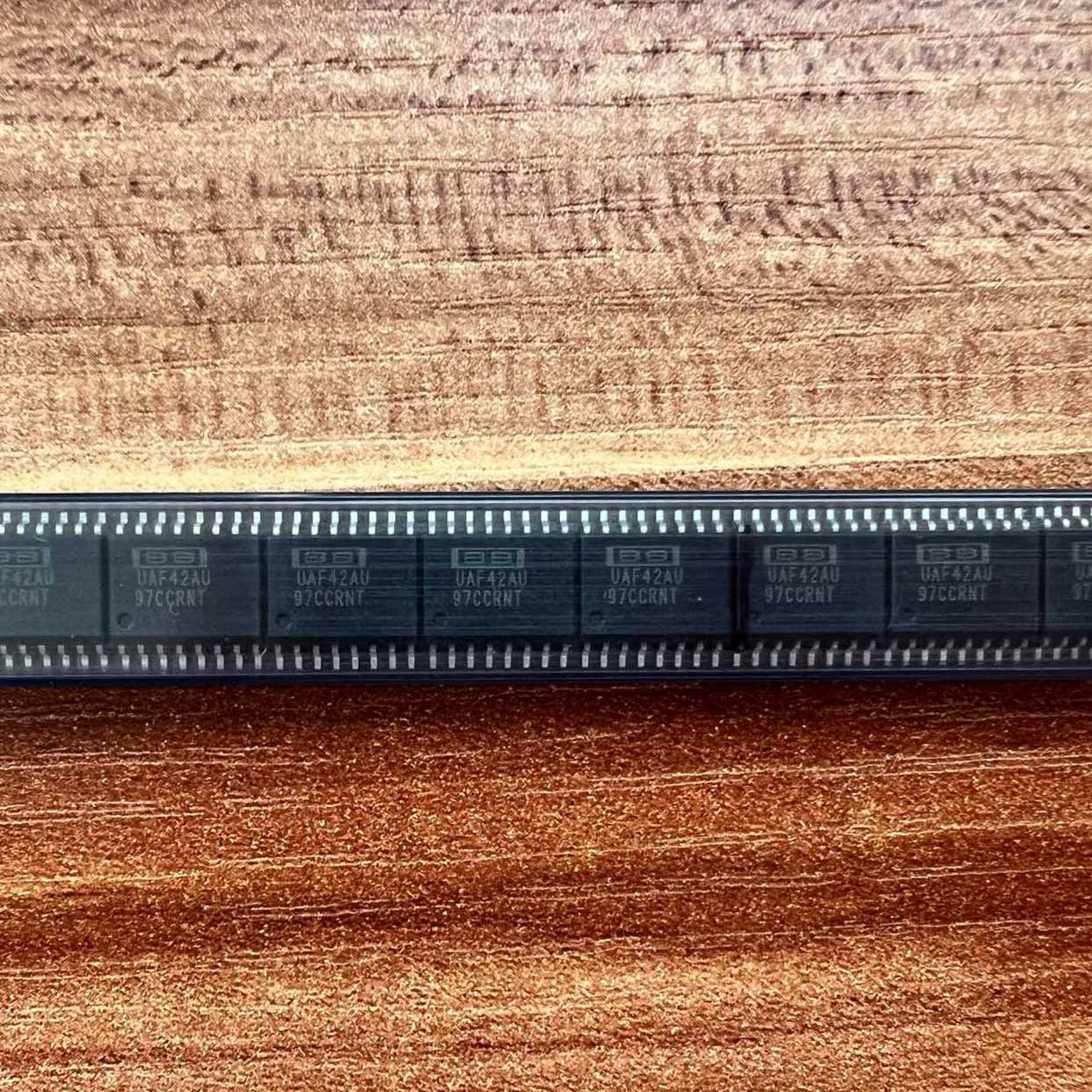
UAF42AU

Universal active filter IC, state-variable topology, LP/HP/BP/Notch, up to 100kHz, Q up to 100, on-chip capacitors, SOIC-14

7280

Effective Inventory

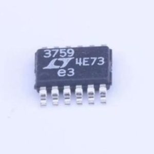
Image for reference only

Manufacturer Part:

UAF42AU

Package:

SOIC-14 (14-lead small outline IC, 3.9mm width, 8.65mm length, 1.27mm pitch)

Brand:

Quality Commitment

Shipping & Payment

Service & Packaging

Product Manual

Description

Product Overview

The UAF42AU is a universal active filter integrated circuit from Texas Instruments, designed to simplify the implementation of high-performance analog filters. Based on the state-variable filter topology, this device can be configured as a low-pass, high-pass, band-pass, band-reject (notch), or all-pass filter by selecting appropriate external resistors and capacitors.

The UAF42AU integrates two operational amplifiers, two integrators, and a summing amplifier on a single monolithic chip, along with on-chip 1000pF polypropylene capacitors that provide excellent temperature stability and low loss. The device achieves filter Q factors up to 100 and cutoff frequencies up to 100 kHz, with frequency stability of 50 ppm/°C typical — far superior to filters implemented with general-purpose op-amps and discrete capacitors.

Available in an SOIC-14 surface-mount package, the UAF42AU operates from ±15V or single 30V supplies. Its versatility and performance make it ideal for applications including anti-aliasing filters in data acquisition systems, bandpass filters for communications, audio processing, and industrial signal conditioning where precise filter characteristics are required without the complexity of discrete multi-stage designs.

Key Specifications

Parameter Value
Filter Topology State-variable (biquad)
Filter Types Supported Low-pass, High-pass, Band-pass, Notch, All-pass
Maximum Center Frequency (f0) 100 kHz
Q Factor Range 0.5 to 100
Gain Range Up to 100 V/V
Frequency Stability 50 ppm/°C typical
On-chip Capacitors 2 × 1000 pF (±0.5% matched, polypropylene)
Supply Voltage Range ±9V to ±18V (dual) or 18V to 36V (single)
Supply Current 4.5 mA typical (quiescent)
Slew Rate 8 V/µs typical
Gain-Bandwidth Product 2 MHz typical
THD (Total Harmonic Distortion) 0.02% typical @ 1 kHz
Input Offset Voltage ±5 mV max
Operating Temperature –40°C to +85°C
Package SOIC-14 (surface mount)

Features

  • Universal state-variable filter: LP, HP, BP, Notch, All-pass
  • High frequency stability: 50 ppm/°C typical
  • On-chip 1000 pF polypropylene capacitors (matched to 0.5%)
  • Q factors up to 100
  • Frequencies up to 100 kHz
  • Low total harmonic distortion: 0.02%
  • Wide supply range: ±9V to ±18V
  • Integrates 4 op-amps on one chip
  • Only external resistors needed to set f0, Q, and gain
  • Tunable via external resistors or digital potentiometers
  • SOIC-14 surface-mount package
  • Industrial temperature range: –40°C to +85°C

Applications

  • Anti-aliasing and reconstruction filters for ADC/DAC systems
  • Audio equalization and crossover networks
  • Bandpass filters for communications and telemetry
  • Notch filters for 50/60 Hz line noise rejection
  • Data acquisition and instrumentation systems
  • Medical equipment and biomedical signal processing
  • Industrial process control and signal conditioning
  • Test and measurement equipment
Product Introduction: UAF42AU Product Introduction

The UAF42AU is a high-performance universal active filter integrated circuit from Texas Instruments. It implements the classic state-variable (also known as biquad or KHN) filter topology using four integrated operational amplifiers and two on-chip precision polypropylene capacitors. This integration allows designers to create very high-quality filters with excellent temperature stability using only external resistors to set the filter parameters.

What sets the UAF42 apart from general-purpose op-amp filter implementations is its on-chip 1000pF polypropylene capacitors. Polypropylene capacitors have extremely low dissipation factor (tan δ < 0.0001) and excellent temperature coefficient stability, typically around ±30ppm/°C. When combined with the integrated circuit design, the UAF42 achieves overall frequency stability of approximately 50ppm/°C — roughly an order of magnitude better than can be achieved with standard ceramic capacitors and discrete op-amps. The two on-chip capacitors are also matched to within 0.5%, ensuring consistent filter response across the two integrator stages.

The UAF42AU provides three simultaneous outputs: low-pass, band-pass, and high-pass, all available at the same time from the same filter configuration. By adding external summing resistors, notch (band-reject) and all-pass filters can also be implemented. The cutoff/center frequency (f0), quality factor (Q), and gain (A) are all independently set by external resistor values, providing great design flexibility.

This device is particularly valuable in applications where filter accuracy and stability are critical, such as precision instrumentation, medical equipment, audio processing, and communications systems. Its SOIC-14 package makes it suitable for modern surface-mount PCB designs with limited board space.

Working Principle: UAF42AU Working Principle

The UAF42 is based on the state-variable filter topology (also called the Kerwin-Huelsman-Newcomb or KHN filter), which uses two integrators and a summing amplifier to create a second-order filter response. Here’s how it works:

1. Summing Amplifier (Input Stage): The first op-amp acts as a summing inverter that combines the input signal with feedback from the band-pass and low-pass outputs. The summing junction accepts three inputs: the input signal (through RG), the band-pass output (through RQ), and the low-pass output (through Rf = RG for unity gain LP). This stage sets the overall filter gain and contributes to establishing the Q factor.

2. First Integrator (Band-Pass Stage): The output of the summing amplifier feeds into the first integrator, which consists of an op-amp with an on-chip 1000pF capacitor in the feedback path and an external resistor (R1) at the input. The integrator’s output is the band-pass (BP) response. The transfer function of an integrator is -1/(sRC), which has a magnitude that rolls off at -20dB/decade and provides a 90° phase shift.

3. Second Integrator (Low-Pass Stage): The band-pass output feeds into a second identical integrator (op-amp + 1000pF cap + external resistor R2). This stage integrates again, producing the low-pass (LP) output. Two integrations give a -40dB/decade roll-off, characteristic of a second-order low-pass filter.

4. High-Pass Output Derivation: The high-pass (HP) response is obtained directly from the summing amplifier’s output node. At high frequencies, the integrators attenuate the signal, so the output is dominated by the direct input path through the summing amp — hence the high-pass characteristic.

5. Frequency Setting (f0): The center/cutoff frequency is determined by the integrator resistors and the on-chip capacitors: f0 = 1 / (2π × R × C), where C = 1000pF. For equal resistors R1 = R2 = R, this simplifies to f0 ≈ 159155 / R (with R in ohms, f0 in Hz).

6. Q Factor Setting: The quality factor Q is set by the ratio of the gain resistor to the Q resistor: Q = (RG / RQ) × sqrt(R2/R1). When R1 = R2, Q = RG / RQ. Higher Q gives sharper filter skirts but can increase peaking in the frequency response.

7. Gain Setting: The low-pass gain is set by ALP = RG / Rf (where Rf is the feedback resistor from LP output to summing input). The band-pass gain is ABP = RG / RQ = Q. The high-pass gain is AHP = RG / Rf = ALP.

8. Notch and All-Pass Configurations: A notch filter is created by summing the input signal with the band-pass output through an external summing amplifier. An all-pass filter is realized by combining the low-pass and high-pass outputs in the correct proportions.

Pin Description: UAF42AU Pin Definition and Functions
Pin No. Pin Name Type Function
1 IN+ (Input +) Input Non-inverting input of the summing amplifier. Connect to signal or ground depending on configuration.
2 IN- (Input -) Input Inverting input of the summing amplifier. Connect RG, RQ, and Rf resistors here.
3 HP OUT Output High-pass filter output. Output of the summing amplifier.
4 BP IN Input Input to first integrator (band-pass integrator). Connect resistor R1 from HP OUT to this pin.
5 BP OUT Output Band-pass filter output. Output of first integrator. Connect RQ feedback to IN- pin.
6 LP IN Input Input to second integrator (low-pass integrator). Connect resistor R2 from BP OUT to this pin.
7 V- (VEE) Power Negative supply voltage. Range: -9V to -18V for dual supply. Bypass with 0.1µF ceramic + 10µF tantalum to GND.
8 LP OUT Output Low-pass filter output. Output of second integrator. Connect Rf feedback to IN- pin.
9 C1A Capacitor Connection to on-chip 1000pF capacitor 1, side A (feedback of first integrator). Connect to BP OUT externally.
10 C1B Capacitor Connection to on-chip 1000pF capacitor 1, side B (inverting input of first integrator). Connect to BP IN externally.
11 C2A Capacitor Connection to on-chip 1000pF capacitor 2, side A (feedback of second integrator). Connect to LP OUT externally.
12 C2B Capacitor Connection to on-chip 1000pF capacitor 2, side B (inverting input of second integrator). Connect to LP IN externally.
13 V+ (VCC) Power Positive supply voltage. Range: +9V to +18V for dual supply. Bypass with 0.1µF ceramic + 10µF tantalum to GND.
14 OFFSET N1 Trim Offset null adjustment for integrator 1. Optional: connect 100kΩ trimmer between pin 14 and V-, wiper to BP IN (pin 4).

Package: SOIC-14 (14-lead small outline integrated circuit). 3.90mm body width, 8.65mm body length, 1.27mm lead pitch. Surface-mount device.

Application Scenarios: In which products and applications is UAF42AU used
  • Anti-Aliasing Filters for Data Acquisition: Low-pass filters placed before analog-to-digital converters (ADCs) to remove frequency components above the Nyquist frequency, preventing aliasing artifacts in digitized signals. The UAF42’s high stability ensures consistent cutoff frequency across temperature variations in industrial environments.
  • Audio Equalization and Crossovers: Audio crossover networks for multi-way speaker systems, where precise low-pass, high-pass, and band-pass filter responses are needed to split the audio spectrum to different driver units. Low THD (0.02%) ensures transparent audio quality.
  • Line Noise Rejection (Notch Filters): 50Hz or 60Hz notch filters for removing power-line interference from sensitive biomedical signals (ECG, EEG), instrumentation amplifiers, and sensor signals. The high Q capability (up to 100) allows narrow notch depth without affecting adjacent frequencies.
  • Communications Bandpass Filters: Tunable bandpass filters for telemetry receivers, modem front-ends, and tone detection systems. The center frequency can be adjusted using external resistors or digital potentiometers for adaptive filtering applications.
  • Biomedical Signal Processing: Filtering of physiological signals such as ECG (0.05Hz to 100Hz bandpass), EEG (1Hz to 50Hz), and EMG, where precise filter characteristics and low noise are essential for accurate diagnostic measurements.
  • Reconstruction Filters for DAC Outputs: Post-DAC smoothing filters that remove image frequency components from digital-to-analog converter outputs, producing clean analog signals in audio systems, waveform generators, and control output circuits.
  • Industrial Signal Conditioning: Filtering of sensor outputs (pressure, temperature, flow) in process control systems, removing high-frequency noise and 50/60Hz interference before the signal is processed by PLCs or data acquisition systems.
  • Test and Measurement Equipment: Precision filters in oscilloscopes, spectrum analyzers, and lock-in amplifiers where accurate frequency response and stable filter parameters are required for reliable measurements.
Alternative Models: What chips are recommended as replacements for UAF42AU
Manufacturer Part Number Topology Max f0 Notes
TI UAF42AP State-variable 100 kHz Same die, DIP-14 through-hole package
TI MAX274 4th-order state-variable 150 kHz 4th-order, 8th-order cascade, resistor-tuned
TI MAX275 4th-order state-variable 300 kHz Higher frequency version of MAX274
Linear Tech LTC1562 4th-order elliptic 300 kHz 4 cascaded 2nd-order sections
Linear Tech LTC1068 Switched-capacitor 200 kHz 4th-order, clock-tunable
Analog Devices AD8422 General-purpose op-amp n/a For custom discrete filter designs

Recommend Parts

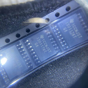
ISO1176TDWR

Isolated RS-485 transceiver, 40Mbps, integrated transformer driver, SOIC-16

Brand: TI

Package: SOIC-16 (DW, wide-body, 10.3 x 10.3 mm)

IN STOCK: 6874pcs

Cargo cycle: 3-7 Days

The minimum order is 1

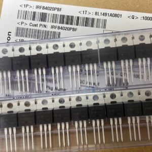
IRFB4020PBF

200V N-Channel HEXFET Power MOSFET, 31A, 68 mΩ RDS(on), TO-220AB

Brand: infineon

Package: TO-220AB

IN STOCK: 14149pcs

Cargo cycle: 3-7 Days

The minimum order is 1

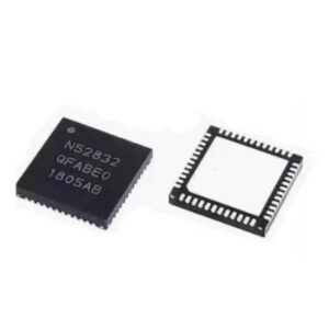
NRF52832-QFAA-T

Nordic BLE SoC, ARM Cortex-M4 @ 64MHz, 64KB Flash, 32KB RAM, QFN-48

Package: See datasheet

IN STOCK: 10958pcs

Cargo cycle: 3-7 Days

The minimum order is 1

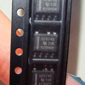
UCC28740DR

CVCC Flyback Controller, 700V startup, opto feedback, <10mW no-load, SOIC-7

Brand: TI

Package: SOIC-7 (4.9 x 3.9 x 1.75 mm)

IN STOCK: 4840pcs

Cargo cycle: 3-7 Days

The minimum order is 1

MMUN2211LT1G

NPN digital transistor, R1=10kΩ R2=10kΩ, 50V, 100mA, SOT-23-3, pre-biased BRT switch

Brand: Onsemi

Package: SOT-23-3 (TO-236, SC-59)

IN STOCK: 8500pcs

Cargo cycle: 3-7 Days

The minimum order is 1

TMS320F2810PBKA

C2000 Delfino DSP controller, 150MHz, 128KB Flash, BGA-179

Brand: TI

Package: BGA-179 (16 x 16 mm, PBK package)

IN STOCK: 3124pcs

Cargo cycle: 3-7 Days

The minimum order is 1