Opens in a new tab

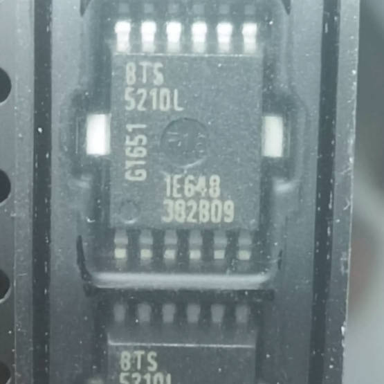
BTS5210LAUMA1

Dual-channel smart high-side power switch, 2×2.4A, 140mΩ, 5.5-40V, DSO-12, Infineon Classic PROFET 24V, digital diagnostics, AEC qualified

6820

Effective Inventory

Image for reference only

Manufacturer Part:

BTS5210LAUMA1

Package:

PG-DSO-12 (12-lead dual small outline package, 7.5mm x 6.4mm body, 1.27mm pitch, surface mount)

Brand:

Quality Commitment

Shipping & Payment

Service & Packaging

Product Manual

Description

Product Overview

The BTS5210LAUMA1 is a dual-channel smart high-side power switch from Infineon Technologies, belonging to the Classic PROFET™ 24V family. This device integrates two independent N-channel vertical power MOSFETs with comprehensive protection and diagnostic features, designed specifically for harsh automotive 24V systems and industrial applications.

Each channel features 140 mΩ maximum on-resistance at 150°C and can deliver up to 2.4 A of nominal load current. The wide operating voltage range of 5.5 V to 40 V makes the BTS5210L suitable for both 12V and 24V automotive systems, as well as 24V industrial control applications. The device can withstand transient voltages up to 55 V, ensuring robustness against load dump and other harsh electrical conditions.

Each channel has its own digital status output (ST1, ST2) that provides fault indication for overtemperature, overload, and open-load conditions. Protection features include active current limitation (5 A minimum), thermal shutdown with dynamic restart, overvoltage clamping, undervoltage detection, loss of ground protection, and reverse battery compatibility with an external resistor. Packaged in a PG-DSO-12 surface-mount package, the BTS5210L is AEC qualified and offers extremely low standby current for minimal battery drain during vehicle park mode.

Key Specifications

Parameter Value
Number of Channels 2 (dual high-side)
RDS(on) per channel @ 150°C 140 mΩ max
Nominal Load Current per Channel 2.4 A
Short-Circuit Current Limit 5 A minimum (6.5 A typical)
Operating Supply Voltage (VS) 5.5 V to 40 V
Transient Voltage (max) 55 V
Output Clamp Voltage 47 V typical (inductive turn-off)
Diagnostic Output Digital status per channel (ST1/ST2)
Open Load Detection OFF-state (3V threshold typical)
Turn-ON Time (ton) 250 µs max
Turn-OFF Time (toff) 270 µs max
Standby Current (all OFF) < 1 µA typical
Logic Input Level CMOS compatible (3.3V/5V)
Maximum Power Dissipation 3.05 W per package
Operating Junction Temperature –40°C to +150°C
Package PG-DSO-12 (surface mount)
Qualification AEC qualified, Automotive grade

Features

  • Dual independent high-side power switches
  • Classic PROFET™ 24V family
  • 140 mΩ max RDS(on) per channel @ 150°C
  • 2.4 A nominal load current per channel
  • Very wide operating voltage: 5.5 V to 40 V
  • 55 V transient voltage capability
  • Digital diagnostic output per channel (ST1/ST2)
  • Active current limitation per channel
  • Thermal shutdown with dynamic restart
  • OFF-state open load detection
  • Overvoltage protection / output clamping
  • Undervoltage detection
  • Loss of ground protection
  • Reverse battery compatible (with external resistor)
  • Fast demagnetization of inductive loads (47V clamp)
  • CMOS compatible inputs
  • Extremely low standby current
  • Optimized EMC performance
  • PG-DSO-12 SMD package
  • AEC qualified, RoHS compliant
  • Long-term availability: planned through 2040

Applications

  • Automotive body electronics (24V trucks/buses)
  • Commercial vehicle lighting and power distribution
  • Industrial 24V control systems and PLCs
  • Solenoid and relay drivers
  • Heating element control
  • DC motor and actuator drivers
  • Replaces electromechanical relays and fuses
  • Heavy-duty vehicle and construction equipment
Product Introduction: BTS5210LAUMA1 Product Introduction

The BTS5210LAUMA1 is a dual-channel intelligent high-side power switch from Infineon Technologies’ Classic PROFET™ 24V product family. This robust device integrates two independent protected high-side switches in a single PG-DSO-12 surface-mount package, designed for demanding 24V automotive and industrial applications.

Each channel features an N-channel vertical power MOSFET with a maximum on-resistance of 140mΩ at 150°C junction temperature, capable of continuously driving up to 2.4A loads. The exceptionally wide operating voltage range from 5.5V to 40V, combined with 55V transient withstand capability, makes this device ideal for both 12V and 24V automotive systems including trucks, buses, and construction equipment where voltage transients are common.

Digital status outputs (ST1 and ST2) provide fault indication for each channel. These open-drain outputs go low during overtemperature, overload, or fault conditions, and can be wire-ORed together to reduce microcontroller I/O count if individual channel diagnostics are not required. The device also supports off-state open-load detection for monitoring bulb integrity or load presence.

Comprehensive protection features include per-channel active current limiting (6.5A typical), thermal shutdown with dynamic restart cycling, output voltage clamping for inductive load demagnetization (47V typical), undervoltage detection, and loss of ground protection. Reverse battery protection can be achieved with a single external ground resistor.

The BTS5210L is manufactured to automotive quality standards and is AEC qualified. With extremely low standby current (less than 1µA), it is well-suited for always-on systems where battery drain during standby must be minimized. Infineon has committed to long-term production availability through at least 2040, making it an excellent choice for programs with long lifecycles.

Working Principle: BTS5210LAUMA1 Working Principle

The BTS5210L operates as two independent smart high-side power switches integrated in a single package. Each channel shares common supply and ground connections but is otherwise independent. Here’s how each channel works:

1. Power MOSFET Stage: Each output channel is built around an N-channel vertical power MOSFET configured as a high-side switch (connecting the load to the positive supply when turned on). A charge pump integrated in each channel generates the voltage above VS needed to drive the N-channel MOSFET gate, requiring no external components.

2. Input Logic (IN1/IN2): Each channel has its own logic input pin. A CMOS-compatible high signal turns the corresponding channel on; a low signal turns it off. The input threshold is compatible with both 3.3V and 5V logic levels. ESD protection diodes are included on all input pins for robustness.

3. Current Limiting: Each channel has an active current limit circuit that monitors the output current and reduces the gate drive if the current exceeds the limit threshold (typically 6.5A, minimum 5A). This prevents supply voltage collapse during short-circuit conditions and limits the power dissipation in the MOSFET during fault events.

4. Thermal Protection: Each channel monitors its own junction temperature. If the temperature exceeds the thermal shutdown threshold (approximately 175°C), the channel is turned off. After cooling below the reset threshold, the channel automatically restarts. For sustained overloads, this creates thermal cycling that maintains a safe average temperature while still providing partial functionality.

5. Status/Diagnostic Output (ST1/ST2): Each channel has an open-drain status pin. During normal operation (channel on, no faults), the status pin is high-impedance (pulled high by external resistor). When an overtemperature or overload fault occurs, the status pin goes low, indicating the fault condition to the system controller.

6. Open Load Detection (OFF-state): When a channel is off, a small current source feeds the output pin. If the load is properly connected, this current flows to ground and the output voltage stays low. If the load is open (disconnected or burned out), the output voltage rises above the detection threshold (3V typical), and the status pin can indicate this condition.

7. Inductive Load Demagnetization: When turning off an inductive load, the output voltage is clamped to approximately 47V (VON(CL)). This allows the energy stored in the inductor to dissipate safely through the power MOSFET, eliminating the need for external freewheeling diodes or snubber circuits.

8. Overvoltage and Undervoltage: Overvoltage protection clamps the output during transient overvoltage conditions. Undervoltage detection monitors the supply voltage and shuts down the channels if VS drops too low, preventing undefined operation at very low supply voltages.

Pin Description: BTS5210LAUMA1 Pin Definition and Functions
Pin No. Pin Name Type Function
1 IN1 Input Logic input for channel 1. High = ON, Low = OFF. CMOS compatible (3.3V/5V). Connect to MCU GPIO.
2 IN2 Input Logic input for channel 2. High = ON, Low = OFF. CMOS compatible (3.3V/5V). Connect to MCU GPIO.
3 ST1 Output Diagnostic status output for channel 1. Open-drain, active-low during fault (overtemperature, overload, open-load). Requires external pull-up resistor (~15kΩ to VCC).
4 ST2 Output Diagnostic status output for channel 2. Open-drain, active-low during fault conditions. Can be wire-ORed with ST1 if only global fault indication is needed.
5 GND Ground Logic/power ground connection. Connect to system ground plane. For reverse battery protection, add a 150Ω resistor (RGND) from this pin to ground.
6 OUT2 Power Output Channel 2 high-side output. Connect to load (load other side to ground). Second output pin for this channel (parallel).
7 OUT2 Power Output Additional channel 2 output pin. Connect together with pin 6 to load for proper current handling.
8 OUT1 Power Output Channel 1 high-side output. Connect to load. Second output pin for channel 1 (parallel).
9 OUT1 Power Output Additional channel 1 output pin. Connect together with pin 8 to load for proper current handling.
10 VS Power Supply voltage input (5.5V to 40V operating). Connect to battery/power supply. Bypass with 100nF ceramic capacitor to GND.
11 VS Power Additional supply pin, internally parallel to pin 10. Must be connected together to supply.
12 VS Power Additional supply pin, internally parallel to pin 10 and 11. All three VS pins must be connected together.

Package: PG-DSO-12 (Plastic Dual Small Outline, 12 leads). Body dimensions: 7.5mm × 6.4mm × 2.35mm (max height). 1.27mm lead pitch. Surface-mount device. Note: All output pins and VS pins with the same name are internally paralleled and must be connected together externally for optimal current and thermal performance.

Application Scenarios: In which products and applications is BTS5210LAUMA1 used
  • Commercial Vehicle Body Electronics: 24V power distribution and load control in trucks, buses, and commercial vehicles for lighting modules, door controls, wiper motors, and heating elements in body control units (BCMs) designed for heavy-duty platforms.
  • Industrial 24V Control Systems: Intelligent load switching in PLC output modules, factory automation equipment, industrial sensors, and 24V process control systems, replacing traditional relay-based output cards with solid-state reliability and diagnostics.
  • Solenoid and Relay Drivers: Driving solenoid valves, contactors, and relay coils in hydraulic systems, pneumatic controls, and industrial automation, where the fast inductive demagnetization (47V clamp) safely handles turn-off transients without external freewheeling diodes.
  • Heavy Equipment and Construction Machinery: Power distribution and auxiliary load control in excavators, bulldozers, cranes, and agricultural equipment, where the wide voltage range and robust protection withstand harsh electrical environments and voltage transients.
  • Heating Element Control: Controlling resistive heating elements in seat heaters, mirror defrosters, fuel pre-heaters, and cabin heating systems, with overcurrent and thermal protection ensuring safe operation even under fault conditions.
  • DC Motor and Actuator Drivers: Driving small DC motors, linear actuators, and gear motors in automotive and industrial applications, with current limiting and thermal protection providing reliable motor protection against stall conditions.
  • Off-Highway and Agricultural Vehicles: Load switching in tractors, harvesters, and other off-highway equipment with 24V electrical systems, where the AEC qualification and wide temperature range ensure reliable operation in extreme environmental conditions.
  • Marine and RV Electrical Systems: 24V power distribution in marine vessels, recreational vehicles, and specialty vehicles, where the device’s protection features and solid-state reliability improve system uptime compared to mechanical relays and fuses.
Alternative Models: What chips are recommended as replacements for BTS5210LAUMA1
Manufacturer Part Number Channels RDS(on)/ch Iout/ch Voltage Notes
Infineon BTS5210L 2 140 mΩ 2.4 A 5.5–40V Base part number (same device)
Infineon BTS5200L 2 200 mΩ 1.2 A 5.5–40V Lower current, lower cost variant
Infineon BTS5090-1EJA 1 90 mΩ 3 A 5–28V Single channel, 12V PROFET+
Infineon BTS7200-2EPA 2 66 mΩ 1.2 A 3.1–28V Newer PROFET+2 generation, analog sense
STMicro VN750PT 2 100 mΩ 3 A 7–36V Dual channel, PowerSO-10
TI TPS2H000A 2 80 mΩ 2.7 A 4.5–40V TI dual high-side, wider voltage

Recommend Parts

ISO1176TDWR

Isolated RS-485 transceiver, 40Mbps, integrated transformer driver, SOIC-16

Brand: TI

Package: SOIC-16 (DW, wide-body, 10.3 x 10.3 mm)

IN STOCK: 6874pcs

Cargo cycle: 3-7 Days

The minimum order is 1

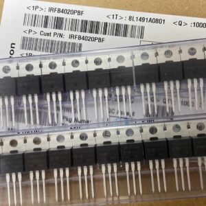
IRFB4020PBF

200V N-Channel HEXFET Power MOSFET, 31A, 68 mΩ RDS(on), TO-220AB

Brand: infineon

Package: TO-220AB

IN STOCK: 14149pcs

Cargo cycle: 3-7 Days

The minimum order is 1

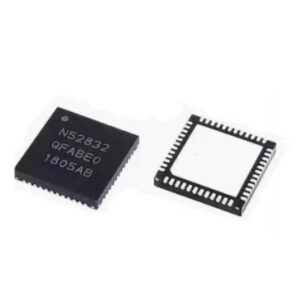
NRF52832-QFAA-T

Nordic BLE SoC, ARM Cortex-M4 @ 64MHz, 64KB Flash, 32KB RAM, QFN-48

Package: See datasheet

IN STOCK: 10958pcs

Cargo cycle: 3-7 Days

The minimum order is 1

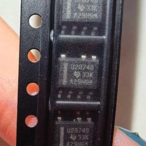
UCC28740DR

CVCC Flyback Controller, 700V startup, opto feedback, <10mW no-load, SOIC-7

Brand: TI

Package: SOIC-7 (4.9 x 3.9 x 1.75 mm)

IN STOCK: 4840pcs

Cargo cycle: 3-7 Days

The minimum order is 1

MMUN2211LT1G

NPN digital transistor, R1=10kΩ R2=10kΩ, 50V, 100mA, SOT-23-3, pre-biased BRT switch

Brand: Onsemi

Package: SOT-23-3 (TO-236, SC-59)

IN STOCK: 8500pcs

Cargo cycle: 3-7 Days

The minimum order is 1

TMS320F2810PBKA

C2000 Delfino DSP controller, 150MHz, 128KB Flash, BGA-179

Brand: TI

Package: BGA-179 (16 x 16 mm, PBK package)

IN STOCK: 3124pcs

Cargo cycle: 3-7 Days

The minimum order is 1