Opens in a new tab

25LC1024-I

Microchip 25-series SPI EEPROM, 1Mbit/128KB, 10MHz, 2.5-5.5V, 256B page, HW+SW write protect, HOLD pin, 1M cycles, industrial -40~85°C, high density

7800

Effective Inventory

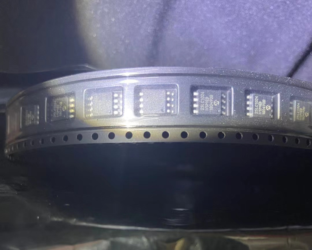
Image for reference only

Manufacturer Part:

25LC1024-I

Package:

8-pin PDIP/SOIC/TSSOP/DFN options (P=PDIP, SN=SOIC-8 150mil, ST=TSSOP-8, MF=DFN-8, etc.)

Brand:

Quality Commitment

Shipping & Payment

Service & Packaging

Product Manual

Description

Product Overview

The 25LC1024-I is a 1 Mbit (128 K x 8) SPI serial EEPROM from Microchip Technology, operating at 2.5 V to 5.5 V supply voltage with industrial temperature range (-40 °C to +85 °C). As the highest-density member of the 25-series SPI EEPROM family, this device offers high-capacity non-volatile memory with a standard SPI interface supporting up to 10 MHz clock frequency.

Organized as 131,072 bytes (128 KB), the 25LC1024 features both byte write and page write capability with a 256-byte page write buffer, enabling up to 256 bytes to be programmed in a single 5 ms write cycle. The device supports SPI modes 0,0 and 1,1, providing compatibility with virtually all SPI host controllers.

Advanced write protection includes a hardware Write-Protect (WP) pin and software-configurable block protection bits (BP0, BP1, BP2) allowing protection of 1/4, 1/2, or the entire memory array. A /HOLD pin enables pausing of serial communication for bus sharing. The device offers exceptional reliability with over 1 million erase/write cycles and greater than 200-year data retention, making it ideal for high-endurance industrial data logging, firmware storage, and automotive applications.

Key Specifications

Parameter Value
Memory Type SPI Serial EEPROM
Density 1 Mbit (1,024 Kbit / 128 KB)
Organization 131,072 x 8 bits
Interface SPI (Modes 0,0 and 1,1)
Max Clock Frequency 10 MHz
Operating Voltage 2.5 V to 5.5 V
Page Size 256 bytes
Page Write Time 5 ms max (typical 3 ms)
Read Current (max) 3 mA @ 5.5 V, 10 MHz
Standby Current (max) 5 µA
Write Protect HW WP pin + SW block protection (BP0/1/2)
Block Protection Protect none, 1/4, 1/2, or entire array
HOLD Function Yes (/HOLD pin)
Sequential Read Yes (entire array)
Endurance 1,000,000 erase/write cycles
Data Retention > 200 years
ESD Protection > 4,000 V
Operating Temperature -40 °C to +85 °C (industrial, I grade)
Packages 8-pin PDIP, SOIC, TSSOP, DFN

Features

  • 1 Mbit (128 K x 8) SPI serial EEPROM
  • Up to 10 MHz SPI clock frequency
  • SPI modes 0,0 and 1,1 supported
  • 2.5 V to 5.5 V operating voltage
  • 256-byte page write buffer
  • Self-timed auto-erase write cycle
  • 5 ms max page write time
  • Block write protection (BP0, BP1, BP2)
  • Hardware Write-Protect (WP) pin
  • /HOLD pin for pausing serial transfers
  • Sequential read: entire array in one operation
  • Power-on reset and brown-out protection
  • Low power CMOS technology
  • 3 mA max active current
  • 5 µA max standby current
  • > 1,000,000 erase/write cycles
  • > 200-year data retention
  • > 4 kV ESD protection on all pins
  • Industrial temperature range
  • Multiple package options
  • RoHS compliant, Pb-free
  • Automotive grade versions available

Applications

  • High-end industrial data logging
  • Automotive electronics and telematics
  • High-throughput configuration and data storage
  • Firmware backup and boot memory
  • Medical device data and event logging
  • Smart meters and energy management
  • Networking equipment parameters
  • Sensor calibration and parameter tables
Product Introduction: 25LC1024-I Product Introduction

The 25LC1024-I is a 1 Mbit (128 K x 8-bit) SPI serial EEPROM from Microchip Technology, representing the highest-density member of the 25-series SPI EEPROM family. The -I suffix denotes industrial temperature range (-40°C to +85°C), and the LC designation indicates 2.5 V minimum operating voltage.

Organized as 131,072 bytes (128 KB), the 25LC1024 provides substantial non-volatile storage capacity for applications such as high-end data logging, firmware storage, calibration parameters, and configuration data. The SPI interface supports clock frequencies up to 10 MHz, offering significantly higher throughput than I2C-based alternatives for large data transfers.

Both SPI Mode 0 (CPOL=0, CPHA=0) and Mode 3 (CPOL=1, CPHA=1) are supported, ensuring compatibility with virtually all microcontroller SPI peripherals. The 256-byte page write buffer allows efficient block programming, with up to 256 contiguous bytes programmable in a single 5 ms self-timed write cycle. Sequential read allows the entire memory array to be read continuously after a single address setup, maximizing data throughput.

Write protection is comprehensive: a hardware Write-Protect (WP) pin combined with software-configurable block protection bits (BP0, BP1, BP2) in the status register allows protecting none, one-quarter, one-half, or the entire memory array. This flexible protection scheme enables partitioning of the memory into protected and unprotected regions. A /HOLD pin allows the master to pause a serial transfer without resetting the communication sequence, useful when a higher-priority device needs to use the SPI bus.

The device features built-in power-on reset and brown-out protection to prevent corrupt writes during power supply transitions. With over 1 million erase/write cycles per byte and greater than 200-year data retention, the 25LC1024 offers exceptional reliability for long-lifecycle products. It is available in multiple package options including PDIP, SOIC, TSSOP, and DFN to suit various board design requirements.

Working Principle: 25LC1024-I Working Principle

The 25LC1024 is a 1 Mbit SPI EEPROM with the same core architecture as other 25-series devices:

1. Memory Array: 131,072 bytes (1 Mbit) of EEPROM memory organized as 128K x 8 bits. 512 pages of 256 bytes each. Data is stored in floating-gate CMOS EEPROM cells with Fowler-Nordheim tunneling for program and erase operations. Non-volatile data retention exceeds 200 years.

2. SPI Interface: 4-wire SPI interface (/CS, SCK, SI, SO). Supports Mode 0 (0,0) and Mode 3 (1,1). Max clock frequency: 10 MHz at 5V supply.

3. Instruction Set: READ, WRITE, WREN (Write Enable), WRDI (Write Disable), RDSR (Read Status Register), WRSR (Write Status Register), plus PE (Page Erase) and CE (Chip Erase) on this larger device.

4. Status Register: 8-bit register containing WIP (Write-In-Progress), WEL (Write Enable Latch), BP0/BP1/BP2 (Block Protection bits), and WPEN (Write Protect Enable). Block protection can cover none, 1/4, 1/2, or the entire array.

5. Write Operation: Byte write or page write (up to 256 bytes). Self-timed write cycle with auto-erase. Max 5 ms, typical 3 ms. Acknowledge via WIP bit polling.

6. Read Operation: Random read after address setup, or sequential read where address auto-increments. Entire 128 KB array can be read in one continuous operation.

7. Power: 3 mA active read current (10 MHz, 5.5V), 5 µA standby current. Built-in power-on reset and brown-out detection for write protection at low voltage.

Pin Description: 25LC1024-I Pin Definition and Functions
Pin # Pin Name Type Description
1 /CS Input Chip Select, active low. Must be pulled low to initiate communication. High = standby mode.
2 SO Output Serial Data Output. Tri-stated when /CS is high or HOLD is active.
3 /WP Input Write Protect, active low. When low and WPEN=1, prevents writes to status register. Internal pull-up.
4 Vss / GND Ground Ground / negative supply pin.
5 SI Input Serial Input. Instructions, addresses, and write data are shifted in on SCK rising edge.
6 SCK Input Serial Clock input from SPI master. Data latched on rising edge in Mode 0.
7 /HOLD Input Hold, active low. Pauses SPI communication without resetting the sequence. Internal pull-up.
8 Vcc Power Positive power supply: 2.5 V to 5.5 V. Decouple with 0.1 µF ceramic cap to GND.

8-Pin Pinout (PDIP/SOIC/TSSOP – top view):

   /CS  1-+---+-8  Vcc
    SO  2-|   |-7  /HOLD
   /WP  3-|   |-6  SCK
   GND  4-+---+-5  SI

Package options: -I/P = 8-pin PDIP (through-hole), -I/SN = SOIC-8 (150mil), -I/ST = TSSOP-8, -I/MF = DFN-8 (2x3mm). Standard 25-series 8-pin pinout. Industrial temperature grade: -40°C to +85°C ambient. RoHS compliant, lead-free.

Application Scenarios: In which products and applications is 25LC1024-I used
  • High-End Industrial Data Logging: Industrial data loggers and process recorders storing high-frequency sampled data with timestamps. The 128 KB capacity and 10 MHz SPI interface enable rapid data recording for extended periods. Page writes (256 bytes) maximize write throughput for bulk data capture.
  • Automotive Electronics and Telematics: Automotive ECUs, black-box event data recorders, and telematics units storing trip history, fault code logs, and driver behavior data. High endurance (1M cycles) supports frequent writes, and automotive AEC-Q100 qualified versions are available for under-hood applications.
  • High-Throughput Configuration and Data Storage: Applications requiring faster data transfer than I2C EEPROMs can provide, such as large configuration tables, image parameters, and user profile storage. The 10 MHz SPI clock is roughly 25x faster than I2C Fast Mode.
  • Firmware Backup and Boot Memory: Secondary firmware storage, boot parameter storage, and FPGA configuration backup where large non-volatile capacity is needed but SPI flash is overkill. 128 KB fits most MCU bootloader and parameter storage needs.
  • Medical Device Data and Event Logging: Patient monitors, diagnostic equipment, and therapeutic devices storing treatment logs, patient data, and device usage history. High data integrity and >200 year retention ensure critical medical data is reliably preserved.
  • Smart Meters and Energy Management: Advanced smart meters storing interval data, TOU tariff tables, load profile records, and network parameters. 128 KB capacity stores months of interval data, and block protection prevents tampering with critical calibration data.
  • Networking Equipment Parameters: Enterprise routers, switches, and gateways storing configuration data, port statistics, firmware images, and security keys. Multiple devices can share the SPI bus using individual /CS signals, with /HOLD for transaction pausing.
  • Sensor Calibration and Parameter Tables: Multi-channel smart sensor systems and industrial transmitters storing comprehensive calibration tables, temperature compensation coefficients, and sensor identification data. Block write protection locks factory calibration, ensuring long-term measurement accuracy.
Alternative Models: What chips are recommended as replacements for 25LC1024-I
Manufacturer Part Number Density Interface Max Clock Page Size Notes
Microchip 25AA1024-I/SN 1 Mbit SPI 10 MHz 256 B 1.8V min (AA version)
Microchip 25LC512-I/SN 512 Kbit SPI 10 MHz 128 B Half density
Microchip 24LC1025-I/SN 1 Mbit I2C 400 kHz 128 B I2C interface alternative
STMicro M95M01-DRMN3TP 1 Mbit SPI 20 MHz 256 B ST M95 series, faster
ON Semi CAT25M01VI-GT3 1 Mbit SPI 20 MHz 256 B ON Semiconductor CAT series

Recommend Parts

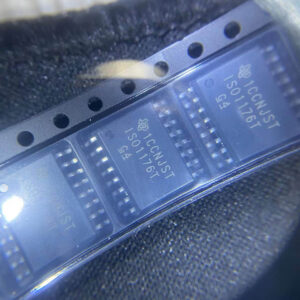
ISO1176TDWR

Isolated RS-485 transceiver, 40Mbps, integrated transformer driver, SOIC-16

Brand: TI

Package: SOIC-16 (DW, wide-body, 10.3 x 10.3 mm)

IN STOCK: 6874pcs

Cargo cycle: 3-7 Days

The minimum order is 1

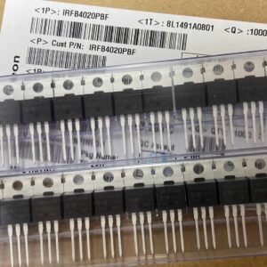
IRFB4020PBF

200V N-Channel HEXFET Power MOSFET, 31A, 68 mΩ RDS(on), TO-220AB

Brand: infineon

Package: TO-220AB

IN STOCK: 14149pcs

Cargo cycle: 3-7 Days

The minimum order is 1

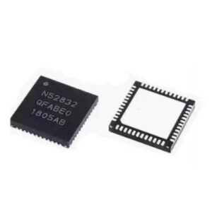
NRF52832-QFAA-T

Nordic BLE SoC, ARM Cortex-M4 @ 64MHz, 64KB Flash, 32KB RAM, QFN-48

Package: See datasheet

IN STOCK: 10958pcs

Cargo cycle: 3-7 Days

The minimum order is 1

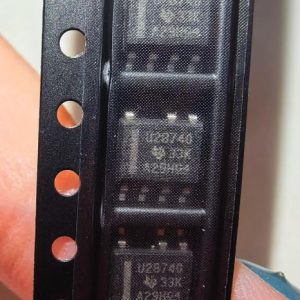
UCC28740DR

CVCC Flyback Controller, 700V startup, opto feedback, <10mW no-load, SOIC-7

Brand: TI

Package: SOIC-7 (4.9 x 3.9 x 1.75 mm)

IN STOCK: 4840pcs

Cargo cycle: 3-7 Days

The minimum order is 1

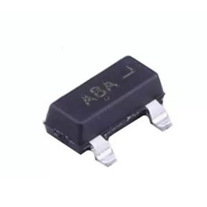
MMUN2211LT1G

NPN digital transistor, R1=10kΩ R2=10kΩ, 50V, 100mA, SOT-23-3, pre-biased BRT switch

Brand: Onsemi

Package: SOT-23-3 (TO-236, SC-59)

IN STOCK: 8500pcs

Cargo cycle: 3-7 Days

The minimum order is 1

TMS320F2810PBKA

C2000 Delfino DSP controller, 150MHz, 128KB Flash, BGA-179

Brand: TI

Package: BGA-179 (16 x 16 mm, PBK package)

IN STOCK: 3124pcs

Cargo cycle: 3-7 Days

The minimum order is 1