Opens in a new tab

INA219AIDCNR

Bidirectional current/power monitor, I2C, 0-26V, 12-bit, PGA, SOT-23-8

12000

Effective Inventory

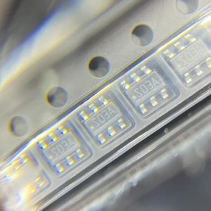
Image for reference only

Manufacturer Part:

INA219AIDCNR

Package:

SOT-23-8 (2.9 x 2.8 x 1.45mm, 0.65mm pitch)

Brand:

Quality Commitment

Shipping & Payment

Service & Packaging

Product Manual

Description

Product Overview

The INA219AIDCNR is a bidirectional current/power monitor with I2C interface from Texas Instruments, sensing bus voltages from 0 to 26V with 12-bit ADC, programmable PGA, and integrated math engine in a SOT-23-8 package.

Key Specifications

Bus Voltage Range 0V to 26V (high-side sensing)
Shunt Voltage Range ±40mV, ±80mV, ±160mV, ±320mV (PGA)
ADC Resolution 12-bit (programmable 9/10/11/12-bit)
Interface I2C (up to 400kHz Fast Mode, 2.56MHz HS)
I2C Addresses 16 programmable (2 address pins)
Accuracy 1% max (A-grade), 0.5% (B-grade)
Supply Voltage 3.0V to 5.5V
Supply Current 0.7mA typical (active), 6µA (power-down)
Conversion Time 84µs (9-bit) to 532µs (12-bit)
Averaging 1, 2, 4, 8, 16, 32, 64, 128 samples
Calibration Register 16-bit (enables direct current/power readout)
Operating Temperature -40°C to +125°C
Package SOT-23-8 (2.9 x 2.8mm)

Features

  • High-side current sensing independent of supply voltage
  • 0V to 26V bus voltage range
  • Bidirectional current measurement
  • Programmable PGA: /1, /2, /4, /8
  • 12-bit ADC with programmable resolution and averaging
  • 16 programmable I2C addresses
  • Calibration register for direct ampere and watt readout
  • Built-in math engine: Current × Voltage = Power
  • One-shot or continuous conversion modes
  • 6µA power-down current

Applications

  • Battery charge/discharge monitoring
  • Server and telecom power rail monitoring
  • Solar panel and wind turbine power measurement
  • Motor current and power monitoring
  • Portable device power budget analysis
Product Introduction: INA219AIDCNR Product Introduction

The INA219AIDCNR from Texas Instruments is a bidirectional current and power monitor with an I2C interface that measures the voltage across a shunt resistor and the bus supply voltage, then computes current and power using an integrated math engine. The device senses bus voltages from 0V to 26V, independent of its own supply voltage (3.0V to 5.5V), making it suitable for high-side current sensing on rails up to 26V. The 12-bit ADC measures shunt voltage with programmable PGA gains (/1, /2, /4, /8) corresponding to ±320mV, ±160mV, ±80mV, and ±40mV full-scale ranges. The calibration register scales the shunt voltage reading to produce direct current values in amperes, and the internal multiplier computes power (Current × Bus Voltage / 5000). Two address pins (A0, A1) allow 16 unique I2C addresses by tying each pin to GND, VS, SDA, or SCL. The A-grade provides 1% max accuracy over temperature. The DCNR suffix denotes the SOT-23-8 package with tape-and-reel packaging.

Working Principle: INA219AIDCNR Working Principle

The INA219AIDCNR measures current by sensing the voltage drop across an external shunt resistor placed between the IN+ and IN- pins. The internal differential amplifier measures this small shunt voltage (typically 0-320mV), and the PGA amplifies it by the selected gain (/1, /2, /4, /8). The 12-bit delta-sigma ADC digitizes the amplified shunt voltage. A separate ADC channel measures the bus voltage at IN- relative to GND (0 to 26V, with 4mV LSB). The conversion results are stored in the Shunt Voltage Register (01h) and Bus Voltage Register (02h). The Calibration Register (05h) is programmed with a value calculated from the desired current LSB and shunt resistance. When the calibration value is programmed, the device automatically calculates Current = Shunt_Voltage × Calibration / 4096 and stores it in the Current Register (04h). The Power Register (03h) is computed as Current × Bus_Voltage / 5000. This eliminates the need for the MCU to perform floating-point multiplication. The Configuration Register (00h) controls PGA gain, ADC resolution/averaging, and operating mode (continuous, triggered, or power-down). In triggered mode, a single conversion is performed on command; in continuous mode, the device converts continuously at the programmed rate.

Pin Description: INA219AIDCNR Pin Definition and Functions
Pin Name Type Description
1 IN+ Input Shunt resistor positive terminal (bus side)
2 IN- Input Shunt resistor negative terminal (load side)
3 GND Power Ground
4 VS Power Supply (3.0V to 5.5V)
5 SDA I/O I2C serial data (open-drain)
6 SCL Input I2C serial clock
7 A1 Input I2C address pin 1 (GND/VS/SDA/SCL)
8 A0 Input I2C address pin 0 (GND/VS/SDA/SCL)

INA219AIDCNR uses the VSSOP-10 (DCN, 3.0×3.0mm) surface-mount package from TI: Pin 1 = A0 (I2C address LSB), Pin 2 = A1 (I2C address MSB), Pin 3 = VIN- (shunt resistor negative), Pin 4 = VIN+ (shunt resistor positive), Pin 5 = GND, Pin 6 = SDA (I2C data), Pin 7 = SCL (I2C clock), Pin 8 = VS (supply voltage, 3-5.5V), Pin 9 = NC (no connect), Pin 10 = NC. The shunt resistor connects between VIN+ and VIN-; the bus voltage is measured at VIN-. Pins A0 and A1 set the I2C address from 0x40 to 0x4F, allowing up to 16 devices on one bus. For high-side current sensing, VIN+ connects to the supply rail and VIN- to the load. The DCN package is footprint-compatible with other VSSOP-10 current sensors.

Application Scenarios: In which products and applications is INA219AIDCNR used
  • Battery Monitoring: High-side sensing up to 26V measures charge/discharge current and computes remaining capacity via power integration
  • Server PSU: 16 I2C addresses allow monitoring 16 separate power rails from one MCU I2C bus
  • Solar Power: Measures panel voltage (up to 26V) and current through shunt; power register computes output directly
  • Motor Drive: Bidirectional measurement captures both drive and regenerative braking current
  • Portable Devices: 6µA power-down and SOT-23-8 footprint minimize impact on space and battery life
Alternative Models: What chips are recommended as replacements for INA219AIDCNR
Model Manufacturer Key Difference Package Specs
INA219BIDCNR TI 0.5% accuracy (B-grade), same package – –
INA226AIDGSR TI 16-bit, ALERT pin, 36V, VSSOP-10 – –
PAC1710-1-AIA-TR onsemi Single, 0-40V, 11-bit, I2C, SOT-23-6 – –
MAX17048GT+T ADI/Maxim Fuel gauge (not just current), I2C, TDFN-8 – –
INA260AIPWR TI 16-bit, integrated shunt, ALERT, TSSOP-16 – –

INA219AIDCNR is a 16-bit I2C current/voltage monitor from TI in VSSOP-10. The INA226 provides similar function with separate VBUS and VSHUNT pins for bidirectional current sensing. The INA260 offers integrated 2mΩ shunt resistor in VQFN-16. The INA3221 provides 3-channel monitoring in VQFN-16. The MAX34407 from ADI/Maxim offers 4-channel power accumulator. The PAC1710 from Microchip provides unidirectional current sensing in SOT-23-6. The INA219B provides improved accuracy with 0.1% gain error.

Recommend Parts

0751.0505

Schurter fuse, 0751.0505

Brand: schurter

Package: See datasheet

IN STOCK: 6768pcs

Cargo cycle: 3-7 Days

The minimum order is 1

TL062CDR

Low-power JFET-input dual op-amp, 1MHz GBW, 30pA Ibias, SOIC-8, ±3.5V to ±18V

Brand: TI

Package: SOIC-8 (3.9 x 4.9 x 1.75mm)

IN STOCK: 11576pcs

Cargo cycle: 3-7 Days

The minimum order is 1

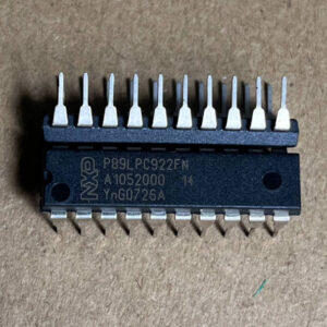
P89LPC922FN

8-bit 80C51 MCU, 8KB Flash, 256B RAM, 20-SSOP

Brand: NXP

Package: SSOP-20 (7.2 x 5.3 mm)

IN STOCK: 12628pcs

Cargo cycle: 3-7 Days

The minimum order is 1

AC0603JR-070RL

Chip Resistor, 0Ω (Zero Ohm Jumper), ±5%, 0603 (1608 Metric), 1/10W (100mW)

Brand: Yageo

Package: 0603 (1608 Metric)

IN STOCK: 100000pcs

Cargo cycle: 3-7 Days

The minimum order is 1

LMR34206FSC5RNXRQ1

42V 2A sync buck, 5V fixed, 2.2MHz, 18uA Iq, AEC-Q100, SOT-563

Brand: TI

Package: SOT-563 (1.6 x 1.2 x 0.55mm)

IN STOCK: 6500pcs

Cargo cycle: 3-7 Days

The minimum order is 1

AO3402

30V N-channel trench MOSFET, SOT-23, 4A, RDS(on) 52m ohm max @ 10V, Qg 10nC, 2.5V gate drive capable, -55C to +150C.

Brand: aosmd

Package: SOT-23 (2.9 x 1.6 x 1.25mm)

IN STOCK: 14066pcs

Cargo cycle: 3-7 Days

The minimum order is 1