Opens in a new tab

SN74LS74AN

Dual D flip-flop, edge-triggered, PRE/CLR, Q+Q̅, 25MHz, PDIP-14

7500

Effective Inventory

Image for reference only

Manufacturer Part:

SN74LS74AN

Package:

PDIP-14 (19.3 x 6.35 x 4.57mm, 2.54mm pitch, through-hole)

Brand:

Quality Commitment

Shipping & Payment

Service & Packaging

Product Manual

Description

Product Overview

The SN74LS74AN from Texas Instruments is a dual D-type positive-edge-triggered flip-flop with preset and clear inputs, complementary outputs, and 25MHz maximum clock frequency in a 14-pin PDIP package.

Key Specifications

Number of Flip-Flops 2 (dual D-type)
Logic Family LS (Low-power Schottky)
Supply Voltage 4.75V to 5.25V (5V nominal)
Trigger Type Positive-edge triggered
Outputs True (Q) and complementary (Q̅) per flip-flop
Preset (PRE) Active-low, asynchronous (sets Q=HIGH)
Clear (CLR) Active-low, asynchronous (sets Q=LOW)
Maximum Clock Frequency 25MHz typical
Propagation Delay (CLK to Q) 25ns typical
Setup Time 15ns minimum before clock edge
Hold Time 0ns minimum after clock edge
Operating Temperature 0°C to +70°C
Package PDIP-14 (19.3 x 6.35mm)

Features

  • Dual D-type positive-edge-triggered flip-flops
  • Independent preset and clear per flip-flop
  • Complementary outputs (Q and Q̅)
  • Asynchronous preset (sets Q=HIGH)
  • Asynchronous clear (sets Q=LOW)
  • 25MHz maximum clock frequency

Applications

  • Frequency division (÷2)
  • Data synchronization
  • One-shot pulse generation
  • Switch debouncing
  • Digital delay and pipelining
Product Introduction: SN74LS74AN Product Introduction

The SN74LS74AN from Texas Instruments contains two independent D-type positive-edge-triggered flip-flops, each with asynchronous preset (PRE) and clear (CLR) inputs and complementary Q/Q̅ outputs. The 74LS74 is the most widely-used D flip-flop in TTL design. On the rising edge of the clock (CLK), the D input is transferred to the Q output. The asynchronous PRE input, when LOW, immediately sets Q=HIGH regardless of CLK or D. The asynchronous CLR input, when LOW, immediately sets Q=LOW. Both PRE and CLR override the clock. The complementary Q̅ output provides the inverted Q value without additional logic. For frequency division, connecting Q̅ to D creates a toggle flip-flop that divides the clock frequency by 2. The A suffix denotes the improved LS version. The N suffix denotes the PDIP-14 through-hole package.

Working Principle: SN74LS74AN Working Principle

Each D-type flip-flop in the SN74LS74AN captures the logic level at its D input on the rising edge of CLK. The captured value appears at Q, and the inverted value at Q̅. Between clock edges, the outputs hold their values. The asynchronous PRE (preset) input, when LOW, forces Q=HIGH and Q̅=LOW regardless of CLK or D. The asynchronous CLR (clear) input, when LOW, forces Q=LOW and Q̅=HIGH. Both PRE and CLR are active-low and override the synchronous (clocked) operation. If both PRE and CLR are simultaneously LOW, both Q and Q̅ go HIGH (invalid state); the state that results when both return HIGH is indeterminate, so this condition should be avoided. For a toggle (÷2) configuration, Q̅ connects to D. Each rising clock edge captures the opposite of the current Q value, causing Q to toggle: 0→1→0→1… The output frequency is half the clock frequency. For a one-shot (monostable) pulse, D is held HIGH, and a brief LOW pulse on CLR clears Q; when CLR returns HIGH, the next clock edge captures D=HIGH, setting Q=HIGH for one clock period.

Pin Description: SN74LS74AN Pin Definition and Functions
Pin Name Type Description
1 1CLR Input Flip-flop 1 clear (active LOW, async)
2 1D Input Flip-flop 1 data input
3 1CLK Input Flip-flop 1 clock (rising edge triggered)
4 1PRE Input Flip-flop 1 preset (active LOW, async)
5 1Q Output Flip-flop 1 true output
6 1Q̅ Output Flip-flop 1 complementary output
7 GND Power Ground
8 2Q̅ Output Flip-flop 2 complementary output
9 2Q Output Flip-flop 2 true output
10 2PRE Input Flip-flop 2 preset (active LOW, async)
11 2CLK Input Flip-flop 2 clock (rising edge triggered)
12 2D Input Flip-flop 2 data input
13 2CLR Input Flip-flop 2 clear (active LOW, async)
14 VCC Power Supply (4.75V to 5.25V)
Application Scenarios: In which products and applications is SN74LS74AN used
  • ÷2 Divider: Q̅ to D; CLK input; Q output = half frequency; cascade for ÷4, ÷8, etc.
  • Data Sync: Asynchronous input → D; system clock → CLK; Q output synchronized to clock edge
  • One-Shot: D=HIGH; trigger on CLR; Q goes HIGH on next clock for exactly one clock period
  • Debounce: Switch through RC filter → D; clock at 100Hz; samples clean state after bounce settles
  • Shift Register: Chain of 74LS74 flip-flops; D of each from Q of previous; shifts data one bit per clock
Alternative Models: What chips are recommended as replacements for SN74LS74AN
Model Manufacturer Key Difference Package Supply
74LS74N TI/Nexperia Original TTL version with 5V-only supply, typical propagation delay 10-15ns DIP-14 5V TTL
74LS74D TI/Nexperia Surface-mount SOIC version of LS with identical logic function SOIC-14 5V TTL
74HC74D TI/Nexperia CMOS version with wide 2-6V supply range, lower power consumption and higher noise immunity SOIC-14 2-6V CMOS
74HC74N TI/Nexperia Through-hole DIP version of HC family for prototyping and repair DIP-14 2-6V CMOS
74HCT74D TI/Nexperia CMOS with TTL-compatible input levels, ideal for mixing with LS devices at 5V SOIC-14 4.5-5.5V TTL-in
74HCT74N TI/Nexperia Through-hole DIP version of HCT family for prototyping and repair DIP-14 4.5-5.5V TTL-in
74AC74D TI/Nexperia Advanced CMOS with 2-6V supply and higher output drive current (24mA vs 6mA for HC) SOIC-14 2-6V CMOS
74AC74N TI/Nexperia Through-hole DIP version of AC family for prototyping and repair DIP-14 2-6V CMOS
74LVC74D TI/Nexperia Low-voltage CMOS for 1.65-3.6V modern logic with 24mA output drive and bus-hold inputs SOIC-14 1.65-3.6V CMOS
74LVC74N TI/Nexperia Through-hole DIP version of LVC family for prototyping and repair DIP-14 1.65-3.6V CMOS

The 7474 is a Dual D-Type Positive-Edge-Triggered Flip-Flop. Family variants span from the original LS TTL (5V only) to modern LVC/AUP (down to 0.8V). HC and HCT versions offer 2-6V CMOS operation with HCT providing TTL-compatible input thresholds for mixed 5V systems. CD4000-series equivalents offer the widest 3-18V supply range at the cost of lower switching speed. DIP packages (N suffix) are through-hole; SOIC (D suffix) and TSSOP are surface-mount.

Recommend Parts

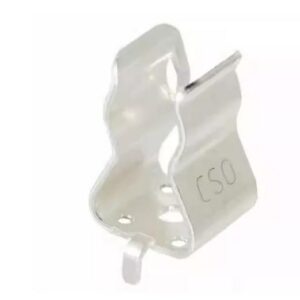
0751.0505

Schurter fuse, 0751.0505

Brand: schurter

Package: See datasheet

IN STOCK: 6768pcs

Cargo cycle: 3-7 Days

The minimum order is 1

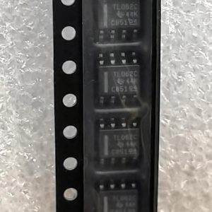
TL062CDR

Low-power JFET-input dual op-amp, 1MHz GBW, 30pA Ibias, SOIC-8, ±3.5V to ±18V

Brand: TI

Package: SOIC-8 (3.9 x 4.9 x 1.75mm)

IN STOCK: 11576pcs

Cargo cycle: 3-7 Days

The minimum order is 1

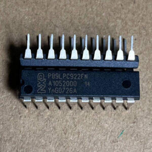
P89LPC922FN

8-bit 80C51 MCU, 8KB Flash, 256B RAM, 20-SSOP

Brand: NXP

Package: SSOP-20 (7.2 x 5.3 mm)

IN STOCK: 12628pcs

Cargo cycle: 3-7 Days

The minimum order is 1

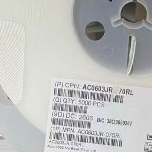
AC0603JR-070RL

Chip Resistor, 0Ω (Zero Ohm Jumper), ±5%, 0603 (1608 Metric), 1/10W (100mW)

Brand: Yageo

Package: 0603 (1608 Metric)

IN STOCK: 100000pcs

Cargo cycle: 3-7 Days

The minimum order is 1

LMR34206FSC5RNXRQ1

42V 2A sync buck, 5V fixed, 2.2MHz, 18uA Iq, AEC-Q100, SOT-563

Brand: TI

Package: SOT-563 (1.6 x 1.2 x 0.55mm)

IN STOCK: 6500pcs

Cargo cycle: 3-7 Days

The minimum order is 1

AO3402

30V N-channel trench MOSFET, SOT-23, 4A, RDS(on) 52m ohm max @ 10V, Qg 10nC, 2.5V gate drive capable, -55C to +150C.

Brand: aosmd

Package: SOT-23 (2.9 x 1.6 x 1.25mm)

IN STOCK: 14066pcs

Cargo cycle: 3-7 Days

The minimum order is 1