Opens in a new tab

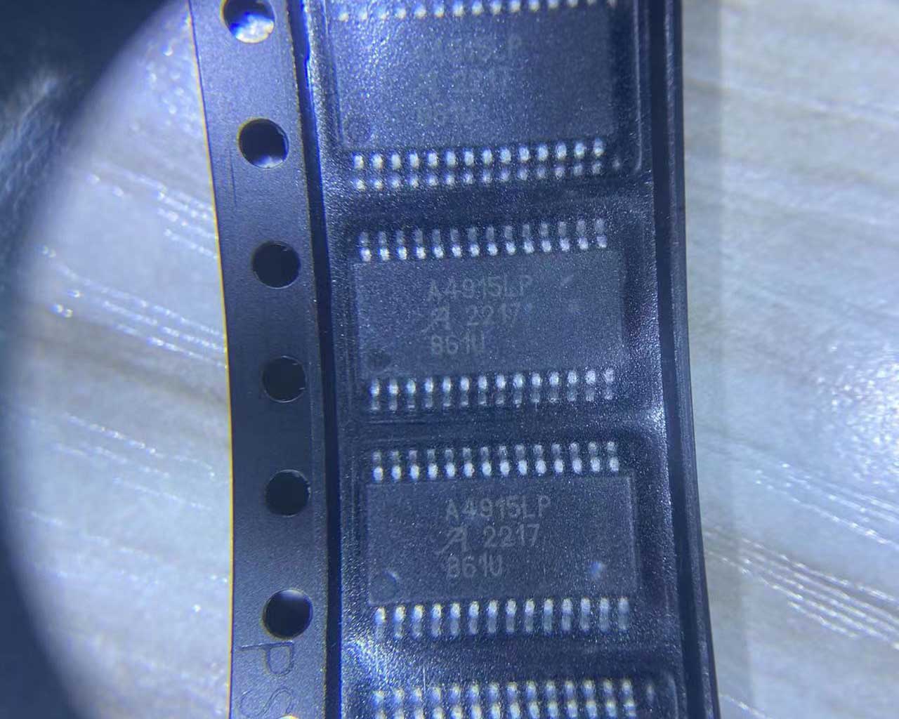
A4915MLPTR-T

Three-phase MOSFET gate driver for BLDC motors, 5-50V supply, 6 N-channel MOSFET drive, Hall sensor inputs, analog speed control, synchronous rectification, 28-TSSOP w/ thermal pad.

4820

Effective Inventory

Image for reference only

Manufacturer Part:

A4915MLPTR-T

Package:

28-TSSOP with Exposed Thermal Pad

Brand:

Product Categories:

Quality Commitment

Shipping & Payment

Service & Packaging

Product Manual

Description

Product Overview

The A4915MLPTR-T is a three-phase MOSFET gate driver IC from Allegro MicroSystems, designed for pulse-width modulated (PWM) current control of 3-phase brushless DC (BLDC) motors. Capable of driving six N-channel power MOSFETs, the A4915 integrates block commutation logic, synchronous rectification control, and a speed input for analog duty cycle control, eliminating the need for a microcontroller PWM output in many simple speed control applications. The device operates from a 5V to 50V supply range with an internal charge pump that ensures full gate drive down to 7V supply (and limited drive down to 5V). Built-in features include Hall sensor inputs for direct commutation, adjustable dead time, cross-conduction protection, undervoltage lockout (UVLO), thermal shutdown, and a low-current sleep mode. Packaged in a 28-pin TSSOP with exposed thermal pad, the A4915MLPTR-T is ideal for battery-powered equipment, power tools, industrial motor control, robotics, and 2W chassis and safety applications where low voltage operation and high efficiency are critical.

Key Specifications

Parameter Value
Load Supply Voltage (VBB) 5 V to 50 V operating range
Logic Supply Voltage (VDD) 3.3 V to 5.5 V
Number of MOSFETs Driven 6 (three-phase, all N-channel)
Gate Drive Type N-Channel MOSFET, bootstrap high-side, charge pump low-side
Gate Drive Voltage Full drive down to 7V VBB; limited drive down to 5V VBB
Commutation Method Block (trapezoidal) commutation via Hall sensor inputs
PWM Control Method Internal PWM via SPEED analog input or external PWM via ENABLE pin
PWM Frequency (Internal) 30 kHz typical (center-aligned)
Control Inputs ENABLE, DIR, BRAKEn, SPEED (analog), HA/HB/HC (Hall)
Synchronous Rectification Internally controlled synchronous rectification
Dead Time Adjustable via external resistor
Protection Features UVLO, cross-over current protection, latched TSD with fault output
Sleep Mode Current Low current sleep when ENABLE held low > tSLEEP
Charge Pump Stabilization Time 3 ms max (coming out of sleep)
Operating Temperature Range -40 degC to +150 degC junction
Package 28-Pin TSSOP with Exposed Thermal Pad (LP package)
Packing 4000 pieces per 13-in reel (tape and reel)
Lead Finish 100% matte-tin (lead-free)

Features

  • 5V to 50V wide supply voltage range for diverse battery and bus voltages
  • Drives six N-channel power MOSFETs for 3-phase BLDC motor control
  • Integrated block commutation logic with Hall sensor inputs
  • Internal charge pump ensures gate drive at low supply voltages
  • Analog SPEED input provides 0-100% PWM duty cycle control
  • Center-aligned PWM for reduced EMI and balanced power dissipation
  • Internally controlled synchronous rectification for improved efficiency
  • Adjustable dead time protection via external resistor
  • Internal UVLO and crossover current protection
  • Latched thermal shutdown (TSD) with fault output indication
  • Brake mode (active-low) for FMEA compliance and emergency stop
  • Low power sleep mode for battery-powered applications
  • Direction control input for forward/reverse motor operation
  • Enable input with external PWM control capability
  • Exposed thermal pad package for enhanced heat dissipation
  • Lead-free, 100% matte-tin plating

Applications

  • Cordless power tools and garden equipment
  • Industrial motor control and drives
  • Robotics and robotic actuators
  • E-bikes and light electric vehicles
  • 2W chassis and safety systems
  • Home appliances with BLDC motors
  • Battery-powered pumps and fans
  • Automotive auxiliary motor drives
  • Consumer electronics with brushless motors
Product Introduction: A4915MLPTR-T Product Introduction

The A4915MLPTR-T is a comprehensive three-phase MOSFET gate driver from Allegro MicroSystems, specifically designed for brushless DC (BLDC) motor control applications using block (trapezoidal) commutation. This highly integrated device simplifies BLDC motor drive designs by incorporating commutation logic, synchronous rectification, PWM control, and comprehensive protection features into a single package, significantly reducing external component count and overall design complexity. Operating from a load supply voltage range of 5V to 50V and a logic supply of 3.3V to 5.5V, the A4915 can drive six external N-channel power MOSFETs in a three-phase bridge configuration. An internal charge pump regulator ensures full gate drive voltage at supply voltages as low as 7V, with limited gate drive capability extending down to 5V, making it well-suited for battery-powered applications. The device features three Hall sensor inputs (HA, HB, HC) for direct connection to Hall-effect position sensors in the motor, with built-in commutation logic that automatically determines which MOSFETs to activate based on the rotor position. This eliminates the need for a microcontroller to perform commutation sequencing, reducing system cost and firmware complexity. Speed control is achieved through a dedicated analog SPEED input pin that controls the internal PWM duty cycle from 0% to 100%, or alternatively through external PWM applied to the ENABLE pin. The PWM operates at 30 kHz typical using a center-aligned architecture that improves power dissipation distribution and helps reduce electromagnetic interference (EMI). Internally controlled synchronous rectification improves efficiency by turning on the appropriate MOSFET during the current decay period instead of relying on the body diode. Adjustable dead time, set via an external resistor, prevents shoot-through (cross-conduction) between high-side and low-side MOSFETs. Comprehensive protection features include undervoltage lockout (UVLO), crossover current protection, and latched thermal shutdown with a dedicated fault output pin. The BRAKEn input provides a brake function that activates all three low-side drivers simultaneously, effectively shorting the motor windings for dynamic braking. The low-power sleep mode draws minimal supply current when the ENABLE pin is held low for an extended period, making the A4915 ideal for battery-operated equipment. Packaged in a 28-pin TSSOP with an exposed thermal pad for enhanced thermal performance, the A4915MLPTR-T is supplied in tape-and-reel packaging with 4000 pieces per reel and features 100% matte-tin lead plating for RoHS compliance.

Working Principle: A4915MLPTR-T Working Principle

The A4915 operates as a complete three-phase BLDC motor controller and gate driver. It receives position feedback from three Hall-effect sensors (HA, HB, HC) mounted in the motor, which indicate the current rotor position. Based on these Hall inputs and the direction (DIR) control signal, the internal commutation logic determines which pair of MOSFETs (one high-side and one low-side on different phases) should be activated to produce torque in the desired direction. This is known as block or trapezoidal commutation, where only two phases are energized at any time. The gate drive for the high-side MOSFETs is provided through bootstrap capacitors connected between each phase output and the corresponding high-side gate drive pin. When the low-side MOSFET of a phase is on, the bootstrap capacitor charges to the VREG voltage through the bootstrap diode. When the high-side MOSFET is subsequently turned on, the bootstrap capacitor provides the voltage source needed to drive the gate above the source voltage (which is at the phase voltage). The low-side gate drives are powered directly from an internal charge pump regulator that generates a regulated voltage above VBB to ensure proper N-channel MOSFET gate drive even at low supply voltages. PWM speed control can be implemented in two modes: internal PWM mode where the SPEED analog input controls the duty cycle of an internally generated 30 kHz carrier, or external PWM mode where the ENABLE pin is pulsed with an external PWM signal. The center-aligned PWM scheme switches both high-side and low-side drivers symmetrically around the center of the PWM period, resulting in lower EMI compared to edge-aligned alternatives. During the PWM off-time, synchronous rectification is implemented by turning on the complementary low-side or high-side MOSFET (depending on current direction), allowing current to recirculate through the low-resistance MOSFET channel rather than the higher-loss body diode, improving overall efficiency. Dead time is inserted between the turn-off of one MOSFET and the turn-on of the complementary MOSFET to prevent shoot-through currents. Protection features include UVLO that disables the outputs if the supply voltage drops below acceptable levels, cross-conduction prevention logic, and thermal shutdown that latches off the device in case of overheating, with the fault condition indicated by the fault output pin. When ENABLE is held low for longer than the sleep timer threshold, the device enters a low-current sleep mode to minimize power consumption in standby.

Pin Description: A4915MLPTR-T Pin Definition and Functions
Pin No. Name Description
1 FAULT Fault output – open-drain output indicating thermal shutdown fault condition
2 VREG Charge pump regulator output – connect decoupling capacitor to GND; provides gate drive supply
3 CP1 Charge pump flying capacitor terminal 1 – connect capacitor between CP1 and CP2
4 CP2 Charge pump flying capacitor terminal 2
5 VDD Logic supply voltage – 3.3V to 5.5V logic supply input
6 SPEED Speed control input – analog voltage (0V to VDD) controls internal PWM duty cycle
7 ENABLE Enable input – HIGH enables outputs; LOW disables; held low > tSLEEP enters sleep mode
8 DIR Direction input – controls motor rotation direction by reversing commutation sequence
9 BRAKEn Brake input (active LOW) – turns on all three low-side drivers for dynamic braking
10 HC Hall sensor C input – position feedback from Hall sensor on phase C
11 HB Hall sensor B input – position feedback from Hall sensor on phase B
12 HA Hall sensor A input – position feedback from Hall sensor on phase A
13 DEAD Dead time adjustment – connect resistor to GND to set dead time value
14 GND Ground – logic and power ground connection
15 GLC Gate drive low-side phase C – connects to gate of low-side MOSFET on phase C
16 SC Source phase C – connects to source of high-side MOSFET and drain of low-side MOSFET
17 GHC Gate drive high-side phase C – connects to gate of high-side MOSFET on phase C
18 CC Bootstrap supply phase C – connect bootstrap capacitor between CC and SC
19 VBB Load supply voltage – main motor supply, 5V to 50V; connect bulk decoupling capacitor
20 CB Bootstrap supply phase B – connect bootstrap capacitor between CB and SB
21 GHB Gate drive high-side phase B – connects to gate of high-side MOSFET on phase B
22 SB Source phase B – phase B output node
23 GLB Gate drive low-side phase B – connects to gate of low-side MOSFET on phase B
24 GL Low-side gate drive supply / internal reference
25 GLA Gate drive low-side phase A – connects to gate of low-side MOSFET on phase A
26 SA Source phase A – phase A output node
27 GHA Gate drive high-side phase A – connects to gate of high-side MOSFET on phase A
28 CA Bootstrap supply phase A – connect bootstrap capacitor between CA and SA
Pad EP Exposed thermal pad – connect to GND for enhanced thermal dissipation
Application Scenarios: In which products and applications is A4915MLPTR-T used
  • Cordless power tools: drills, saws, impact drivers, and garden tools
  • Industrial BLDC motor control and variable speed drives
  • Robotics: robotic arm joints, wheel drives, actuator control
  • E-bikes, electric scooters, and light electric vehicles
  • 2-wheeler chassis and safety systems (brake, steering motors)
  • Home appliances: refrigerators, air conditioners, washing machines
  • Battery-powered pumps and fans for portable equipment
  • Automotive auxiliary motor drives (HVAC blowers, pumps)
  • Consumer electronics: drones, camera gimbals, robotic vacuums
  • Medical equipment and laboratory instrument motor drives
Alternative Models: What chips are recommended as replacements for A4915MLPTR-T
Model Manufacturer Key Difference
A4915METTR-T Allegro Same functionality, 28-QFN 5x5mm package instead of TSSOP
A4919 Allegro Similar 3-phase driver with integrated LDO regulator and direct 6-input control
DRV8301 Texas Instruments 3-phase gate driver with current shunt amps, 60V, similar application
L6234 STMicroelectronics Integrated 3-phase DMOS driver, 52V, 3A output (integrated FETs)
IR2101 Infineon / IR Single half-bridge gate driver, simpler alternative (3 needed for 3-phase)

Recommend Parts

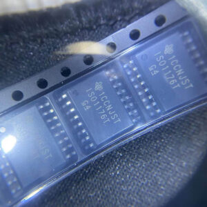
ISO1176TDWR

Isolated RS-485 transceiver, 40Mbps, integrated transformer driver, SOIC-16

Brand: TI

Package: SOIC-16 (DW, wide-body, 10.3 x 10.3 mm)

IN STOCK: 6874pcs

Cargo cycle: 3-7 Days

The minimum order is 1

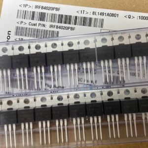
IRFB4020PBF

200V N-Channel HEXFET Power MOSFET, 31A, 68 mΩ RDS(on), TO-220AB

Brand: infineon

Package: TO-220AB

IN STOCK: 14149pcs

Cargo cycle: 3-7 Days

The minimum order is 1

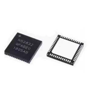
NRF52832-QFAA-T

Nordic BLE SoC, ARM Cortex-M4 @ 64MHz, 64KB Flash, 32KB RAM, QFN-48

Package: See datasheet

IN STOCK: 10958pcs

Cargo cycle: 3-7 Days

The minimum order is 1

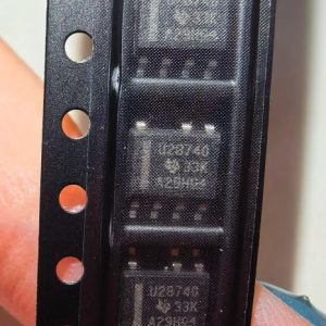
UCC28740DR

CVCC Flyback Controller, 700V startup, opto feedback, <10mW no-load, SOIC-7

Brand: TI

Package: SOIC-7 (4.9 x 3.9 x 1.75 mm)

IN STOCK: 4840pcs

Cargo cycle: 3-7 Days

The minimum order is 1

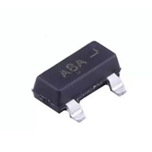
MMUN2211LT1G

NPN digital transistor, R1=10kΩ R2=10kΩ, 50V, 100mA, SOT-23-3, pre-biased BRT switch

Brand: Onsemi

Package: SOT-23-3 (TO-236, SC-59)

IN STOCK: 8500pcs

Cargo cycle: 3-7 Days

The minimum order is 1

TMS320F2810PBKA

C2000 Delfino DSP controller, 150MHz, 128KB Flash, BGA-179

Brand: TI

Package: BGA-179 (16 x 16 mm, PBK package)

IN STOCK: 3124pcs

Cargo cycle: 3-7 Days

The minimum order is 1