Opens in a new tab

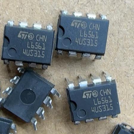
L6561

Transition-mode PFC controller, 8-DIP/SO-8, near-unity PF, OVP/OCP, low startup current, ST

7007

Effective Inventory

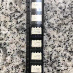
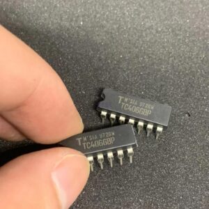
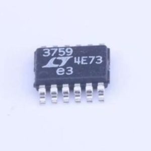
Image for reference only

Manufacturer Part:

L6561

Package:

8-DIP / SO-8

Brand:

Product Categories:

Quality Commitment

Shipping & Payment

Service & Packaging

Product Manual

Description

Product Overview

The L6561 is a transition-mode (TM) Power Factor Correction (PFC) controller designed for AC-DC power supply applications. Manufactured by STMicroelectronics, this device enables power supplies to achieve near-unity power factor and comply with international harmonic current standards (IEC 61000-3-2). Operating in transition mode (also called boundary conduction mode or BCM), the L6561 automatically adjusts switching frequency to maintain the inductor current waveform at the boundary between continuous and discontinuous modes, resulting in zero-current switching turn-on for reduced switching losses.

Key Specifications

Type Transition-Mode PFC Controller
Supply Voltage (VCC) 10.5V ~ 22V
Startup Current 50 µA typical
Operating Current 3 mA typical
Control Mode Transition Mode (BCM)
Output Drive Current ±400 mA (gate drive)
Oscillator (MULT/PFC) Internal reference
OVP Threshold Adjustable via divider
UVLO Threshold 10.5V on / 9.8V off
Package 8-Pin DIP / SO-8
Operating Temperature -25°C ~ +125°C

Features

  • Transition mode (TM/BCM) PFC control
  • Near-unity power factor achievable
  • Zero-current switching (ZCS) turn-on
  • Low start-up current: 50µA
  • Low operating current: 3mA
  • Overvoltage protection (OVP)
  • Overcurrent protection (OCP)
  • Disable function for on/off control
  • Output stage: ±400mA gate drive
  • Internal over-temperature protection
  • Very few external components
  • RoHS compliant

Applications

  • Switch-mode power supply PFC pre-regulators
  • AC-DC adapters and chargers
  • LCD TV and monitor power supplies
  • LED driver power factor correction
  • Server and telecom power supplies
  • Industrial power systems
  • Home appliance power supplies
  • Lighting ballast PFC stages
Product Introduction: L6561 Product Introduction

The L6561 is a transition-mode (also known as boundary conduction mode or BCM) power factor correction controller from STMicroelectronics. It is designed to drive a boost converter stage in AC-DC power supplies to achieve near-unity power factor (>0.99) and low total harmonic distortion (THD), enabling compliance with IEC 61000-3-2 and other international harmonic current standards. In transition mode, the inductor current always returns to zero before the next switching cycle begins, and the IC automatically adjusts the switching frequency to maintain this boundary condition. This mode of operation offers several advantages: zero-current switching at turn-on (reducing switching losses and EMI), simpler control compared to continuous conduction mode (CCM), and no need for a current sense transformer. The L6561 features very low startup current (50µA) and low operating current (3mA), minimizing power loss and enabling efficient standby operation. The integrated gate driver can source/sink up to 400mA, capable of driving external power MOSFETs directly. Protection features include output overvoltage protection (OVP), cycle-by-cycle current limiting, and thermal shutdown. The device can be disabled via the MULT pin for power management or fault conditions. Available in both 8-pin DIP (through-hole) and SO-8 (surface-mount) packages, the L6561 is widely used in switch-mode power supplies for consumer electronics, industrial equipment, LED lighting, and telecom systems requiring power factor correction.

Working Principle: L6561 Working Principle

The L6561 implements a transition-mode (TM) power factor correction controller that shapes the input current to follow the AC line voltage waveform, achieving near-unity power factor. The core principle is a boost converter where the switch is turned on when the inductor current reaches zero (zero-current detection) and turned off when it reaches a peak value set by the instantaneous line voltage. This results in a triangular inductor current waveform whose average value follows the input voltage envelope, creating a resistive input impedance. The control loop works as follows: (1) The error amplifier compares the output voltage (via a resistive divider on the INV pin) with an internal 2.5V reference, generating an error signal. (2) This error signal is multiplied by a signal proportional to the instantaneous AC line voltage (from the MULT pin, which monitors the rectified input voltage). (3) The multiplier output sets the current reference level for each switching cycle — higher at the line voltage peak, lower near zero crossing. (4) When the switch turns on, the inductor current ramps up. When this current (sensed via a resistor on the CS pin) reaches the reference level, the switch turns off. (5) When the switch is off, the inductor current ramps down, delivering energy to the output. When the current reaches zero (detected by the ZCD pin monitoring the auxiliary winding), the switch turns on again and the cycle repeats. The switching frequency thus varies with line voltage and load — highest near the line zero crossings and lowest at the peaks. This variable-frequency operation is inherent to TM/BCM PFC. The zero-current switching at turn-on reduces switching losses and EMI emissions. The overall result is an input current that closely tracks the input voltage waveform, achieving high power factor and low harmonic distortion.

Pin Description: L6561 Pin Definition and Functions
Pin Number Pin Name Type Description
1 INV Input Inverting input of error amplifier (output voltage feedback)
2 COMP I/O Error amplifier output (compensation network)
3 MULT Input Multiplier input (rectified line voltage sensing)
4 CS Input Current sense input (switch current monitoring)
5 ZCD Input Zero-current detection (inductor demagnetization sense)
6 GND Power Ground (0V)
7 GD Output Gate drive output (drives PFC MOSFET gate)
8 VCC Power Supply voltage (10.5V-22V)
Application Scenarios: In which products and applications is L6561 used
  • AC-DC SMPS PFC pre-regulator stages
  • LCD/LED TV and monitor power supplies
  • Notebook adapter and charger front-ends
  • LED street lighting driver PFC
  • Server and telecom power modules
  • Industrial control power supplies
  • Home appliance power converters
  • Fluorescent and HID lighting ballasts
Alternative Models: What chips are recommended as replacements for L6561
Manufacturer Part Number Description
STMicroelectronics L6562 TM PFC controller with improved features, SO-8
STMicroelectronics L6563 TM PFC with PFC+Flyback combo
Infineon ICE1PCS01 TM PFC controller, DSO-8
ON Semiconductor NCP1653 TM PFC controller, 8-pin

Recommend Parts

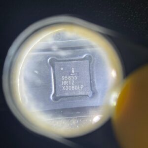
ISL95855HRTZ-T

IMVP8 3+2+1 phase buck controller, R3 technology, 4.5-25V input, 48-TQFN

Brand: Renesas

Package: 48-TQFN (6×6 mm, exposed pad)

IN STOCK: 2156pcs

Cargo cycle: 3-7 Days

The minimum order is 1

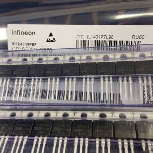
IRFB4019PBF

150V N-Channel HEXFET Power MOSFET, 47A, 34 mΩ RDS(on), TO-220AB

Brand: infineon

Package: TO-220AB

IN STOCK: 2409pcs

Cargo cycle: 3-7 Days

The minimum order is 1

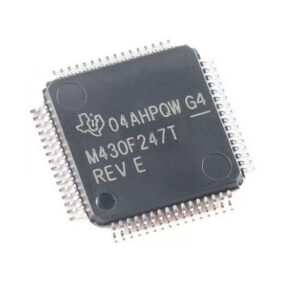
MSP430F247TPMR

TI MSP430 MCU, 16-bit RISC, 92KB Flash, 8KB RAM, 16MHz, LQFP-64

Package: See datasheet

IN STOCK: 13371pcs

Cargo cycle: 3-7 Days

The minimum order is 1

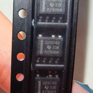
UCC28740DR

CVCC Flyback Controller, 700V startup, opto feedback, <10mW no-load, SOIC-7

Brand: TI

Package: SOIC-7 (4.9 x 3.9 x 1.75 mm)

IN STOCK: 4840pcs

Cargo cycle: 3-7 Days

The minimum order is 1

MMUN2211LT1G

NPN digital transistor, R1=10kΩ R2=10kΩ, 50V, 100mA, SOT-23-3, pre-biased BRT switch

Brand: Onsemi

Package: SOT-23-3 (TO-236, SC-59)

IN STOCK: 8500pcs

Cargo cycle: 3-7 Days

The minimum order is 1

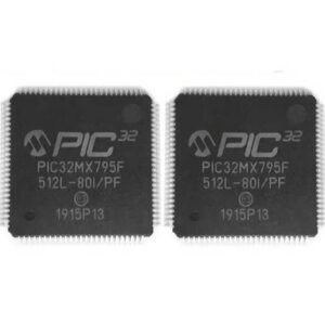
PIC32MX795F512L-80I/PF

32-bit PIC32MX MCU with Ethernet/CAN/USB, 80MHz, 512KB Flash, TQFP-100, industrial

Brand: MICROCHIP

Package: TQFP-100 (14 x 14 mm)

IN STOCK: 7912pcs

Cargo cycle: 3-7 Days

The minimum order is 1