
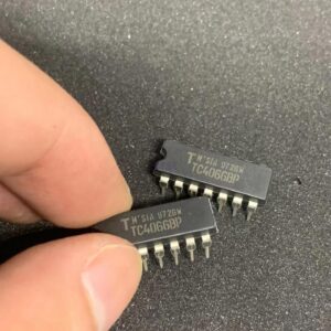
Product Overview
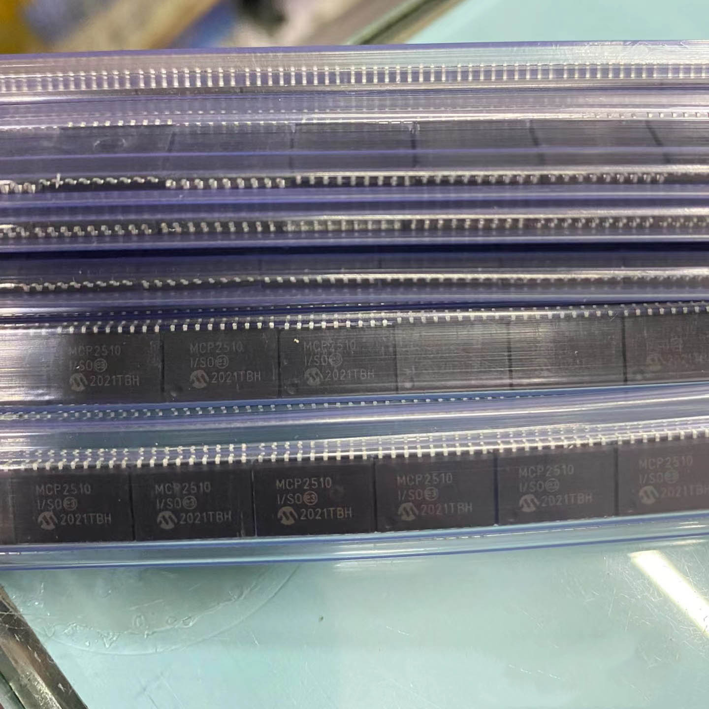
The MCP2510-I is a standalone CAN (Controller Area Network) controller with SPI interface from Microchip Technology. This device implements the CAN 2.0B specification, supporting both standard and extended data frames at data rates up to 1 Mb/s. It features two receive buffers, three transmit buffers, and six acceptance filters with two masks. The MCP2510-I operates from 2.7V to 5.5V and comes in an 18-pin PDIP/SOIC package, making it ideal for adding CAN connectivity to microcontroller systems via SPI.
Key Specifications
| Manufacturer | Microchip Technology |
| Protocol | CAN 2.0B (ISO 11898) |
| Data Rate | Up to 1 Mb/s |
| Interface | SPI (up to 10 MHz) |
| Supply Voltage | 2.7V to 5.5V |
| Operating Temperature | -40°C to +85°C |
| Package | PDIP-18 / SOIC-18 |
| Receive Buffers | 2 (with prioritization) |
| Transmit Buffers | 3 (with prioritization) |
| Acceptance Filters | 6 (with 2 masks) |
| Interrupt Output | Multi-source, selectable |
Features
- Implements CAN 2.0B protocol (standard & extended frames)
- Data rates up to 1 Mb/s
- SPI interface (up to 10 MHz clock)
- Two receive buffers with prioritized message storage
- Three transmit buffers with abort capability
- Six 29-bit acceptance filters and two masks
- One-shot transmission mode
- Programmable clock output for MCU
- Low-power sleep mode with wake-up filter
- Extended temperature range: -40°C to +85°C
- Automotive and industrial control networks
- CAN bus gateways and bridges
- Industrial sensor networks
- Building automation and HVAC
- Medical equipment networking
- Embedded systems requiring CAN connectivity
- Automotive body electronics and powertrain control modules
- Industrial automation networks and fieldbus systems
- CAN bus gateways and protocol converters
- Building automation and HVAC control systems
- Medical device networking and patient monitoring
- Marine and aerospace data bus systems
Applications
Product Introduction: MCP2510-I Product Introduction
The MCP2510-I is a fully integrated CAN (Controller Area Network) controller from Microchip Technology that implements the CAN 2.0B specification. Designed to interface with microcontrollers via a Serial Peripheral Interface (SPI), it provides a simple way to add CAN connectivity to virtually any microcontroller-based system. The MCP2510 supports both standard (11-bit identifier) and extended (29-bit identifier) data frames and remote frames at baud rates up to 1 Mb/s. It features two receive buffers with prioritized message storage, three transmit buffers with configurable transmission priority and abort capability, and six acceptance filters with two acceptance masks to reduce CPU overhead. The device provides an interrupt output pin that can be configured to trigger on multiple events including receive buffer full, transmit buffer empty, error conditions, and bus-off state. A programmable clock output is available to drive the host microcontroller or other system components. The MCP2510 operates from a 2.7V to 5.5V supply, supporting both 3.3V and 5V system designs, and features a low-power sleep mode with wake-on-bus-activity for power-sensitive applications. The ‘I’ suffix indicates the industrial temperature range of -40°C to +85°C.
Working Principle: MCP2510-I Working Principle
The MCP2510-I operates as an independent CAN protocol controller that handles all layers of the CAN 2.0B protocol including bit timing, CRC generation/checking, error handling, and message filtering. The host microcontroller communicates with the MCP2510 through the SPI interface, reading and writing to internal registers that configure the device and transfer message data. On the transmit side, the CPU loads a message into one of three transmit buffers, sets the priority, and initiates transmission by setting the TXREQ bit. The MCP2510 then handles the complete CAN frame transmission including arbitration, bit stuffing, CRC generation, and acknowledgment checking. On the receive side, incoming CAN messages are processed by the protocol engine, which checks the message identifier against the acceptance filters. If a match is found, the complete message (identifier, data length code, data bytes, and CRC) is stored in one of the two receive buffers and an interrupt is generated. The two receive buffers allow reception of back-to-back messages without CPU intervention. The six acceptance filters can be individually configured to match specific message identifiers, and the two masks define which bits of the identifier are compared against the filter values. This hardware filtering significantly reduces the host CPU load by only passing relevant messages. The bit timing is fully programmable through the CNF1, CNF2, and CNF3 configuration registers, supporting standard CAN baud rates from 10 kb/s up to 1 Mb/s with proper oscillator selection.
Pin Description: MCP2510-I Pin Definition and Functions
| Pin | Name | Type | Function |
|---|---|---|---|
| 1 | TXCAN | Output | CAN transmit output (to CAN transceiver) |
| 2 | RXCAN | Input | CAN receive input (from CAN transceiver) |
| 3 | CLKOUT | Output | Programmable clock output |
| 4 | TX0RTS | Input | Transmit buffer 0 request-to-send input |
| 5 | TX1RTS | Input | Transmit buffer 1 request-to-send input |
| 6 | TX2RTS | Input | Transmit buffer 2 request-to-send input |
| 7 | OSC2 | Output | Crystal oscillator output |
| 8 | OSC1 | Input | Crystal oscillator input |
| 9 | VSS | Ground | Ground |
| 10 | RX0BF | Output | Receive buffer 0 full interrupt output |
| 11 | RX1BF | Output | Receive buffer 1 full interrupt output |
| 12 | INT | Output | Main interrupt output (active-low) |
| 13 | SCK | Input | SPI serial clock input |
| 14 | SI | Input | SPI serial data input |
| 15 | SO | Output | SPI serial data output |
| 16 | CS | Input | SPI chip select input (active-low) |
| 17 | RESET | Input | Master reset input (active-low) |
| 18 | VDD | Power | Positive supply voltage (2.7V to 5.5V) |
Application Scenarios: In which products and applications is MCP2510-I used
Alternative Models: What chips are recommended as replacements for MCP2510-I
| Manufacturer | Part Number | Package | Notes |
|---|---|---|---|
| Microchip | MCP2515-I/SO | SOIC-18 | CAN 2.0B controller with faster SPI |
| Microchip | MCP25625 | SOIC-14 | CAN controller + transceiver in one package |
| Texas Instruments | MCP2551 | SOIC-8 | CAN transceiver (external required) |
| NXP | SJA1000T | DIP-28 | Standalone CAN controller alternative |
| STMicroelectronics | L9617 | SOIC-8 | CAN transceiver |
Recommend Parts
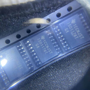
ISO1176TDWR
Isolated RS-485 transceiver, 40Mbps, integrated transformer driver, SOIC-16
Brand: TI
Package: SOIC-16 (DW, wide-body, 10.3 x 10.3 mm)
IN STOCK: 6874pcs
Cargo cycle: 3-7 Days
The minimum order is 1
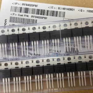
IRFB4020PBF
200V N-Channel HEXFET Power MOSFET, 31A, 68 mΩ RDS(on), TO-220AB
Brand: infineon
Package: TO-220AB
IN STOCK: 14149pcs
Cargo cycle: 3-7 Days
The minimum order is 1
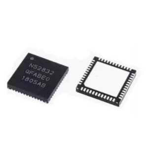
NRF52832-QFAA-T
Nordic BLE SoC, ARM Cortex-M4 @ 64MHz, 64KB Flash, 32KB RAM, QFN-48
Brand: Nordic Semiconductor
Package: See datasheet
IN STOCK: 10958pcs
Cargo cycle: 3-7 Days
The minimum order is 1
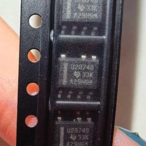
UCC28740DR
CVCC Flyback Controller, 700V startup, opto feedback, <10mW no-load, SOIC-7
Brand: TI
Package: SOIC-7 (4.9 x 3.9 x 1.75 mm)
IN STOCK: 4840pcs
Cargo cycle: 3-7 Days
The minimum order is 1
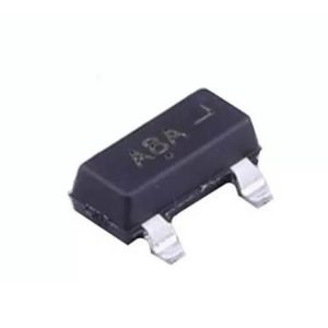
MMUN2211LT1G
NPN digital transistor, R1=10kΩ R2=10kΩ, 50V, 100mA, SOT-23-3, pre-biased BRT switch
Brand: Onsemi
Package: SOT-23-3 (TO-236, SC-59)
IN STOCK: 8500pcs
Cargo cycle: 3-7 Days
The minimum order is 1
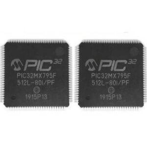
PIC32MX795F512L-80I/PF
32-bit PIC32MX MCU with Ethernet/CAN/USB, 80MHz, 512KB Flash, TQFP-100, industrial
Brand: MICROCHIP
Package: TQFP-100 (14 x 14 mm)
IN STOCK: 7912pcs
Cargo cycle: 3-7 Days
The minimum order is 1