
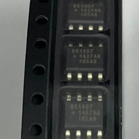
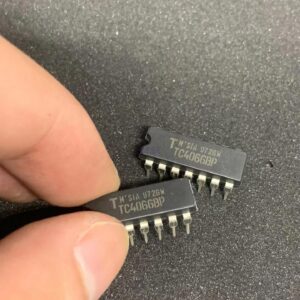
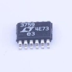
The DS1307Z+T&R from Analog Devices (formerly Maxim Integrated) is a 64 x 8 serial I2C real-time clock (RTC) with 56 bytes of battery-backed NV SRAM in an 8-pin SOIC (150 mil) package with tape and reel packaging. Key specifications: complete clock/calendar counting seconds, minutes, hours, day, date, month, and year with leap-year compensation valid up to 2100; BCD-coded time and date registers; 56 bytes of battery-backed general-purpose NV SRAM with unlimited writes; I2C serial interface (standard mode 100 kHz only); slave address 0x68 (1101000); programmable square-wave output at 1 Hz, 4.096 kHz, 8.192 kHz, or 32.768 kHz; automatic power-fail detect and switch circuitry; battery backup current less than 500 nA typical with oscillator running; supply voltage 4.5 V to 5.5 V; battery backup voltage 2 V to 3.5 V (typically 3 V lithium coin cell); operating temperature 0 to +70 degrees C (Z suffix commercial grade); UL recognized component. The Z suffix denotes SOIC-8 package, + denotes lead-free/RoHS compliant, T and R denotes tape and reel packaging.
Home » Analog Linear ICs, Integrated Circuits ICs » DS1307Z+T&R
DS1307Z+T&R
I2C RTC, 56B NV SRAM, BCD clock/calendar, SQW out 1Hz-32kHz, 500nA bat backup, 4.5-5.5V, SOIC-8, 0~70C, T&R
Effective Inventory
Manufacturer Part:
DS1307Z+T&R
Package:
SOIC-8 (150 mil) (4.9 x 3.9 mm, 1.27mm pitch)
Brand:
Product Categories:
Quality Commitment
Shipping & Payment
Service & Packaging
Product Manual
Other recommendations you may be interested in.
Description
Product Introduction: DS1307Z+T&R Product Introduction
The DS1307Z+T&R from Analog Devices (formerly Maxim Integrated/Dallas Semiconductor) is one of the most widely used real-time clock ICs in the electronics industry. It provides a complete BCD-coded clock/calendar with automatic leap-year compensation, plus 56 bytes of battery-backed non-volatile SRAM, all accessible through a simple I2C serial interface.
The DS1307 is the classic Arduino RTC chip, popularized by the widely-used DS1307 breakout board modules that combine the DS1307 with a 32.768 kHz crystal and a CR2032 coin cell battery. These modules are among the most common and affordable RTC solutions for hobbyist and maker projects.
The clock/calendar function provides seconds, minutes, hours (12-hour with AM/PM or 24-hour format), day of the week, date, month, and year. The year field is two digits (00-99) with automatic leap-year compensation, valid up to year 2100. The time and date registers are located at addresses 00h-06h in the register map.
The 56 bytes of NV SRAM (addresses 08h-3Fh) are battery-backed and provide unlimited read/write cycles, unlike EEPROM which has limited write endurance. This makes the SRAM suitable for storing configuration data, calibration values, or logging data that changes frequently.
The I2C interface operates in standard mode (100 kHz maximum). The DS1307 always operates as a slave device with a fixed 7-bit address of 0x68 (binary 1101000). The interface supports both byte-write and burst-read operations, allowing the entire time/date to be read in a single I2C transaction.
The automatic power-fail detect and switch circuitry monitors the VCC supply. When VCC drops below the battery voltage (VBAT), the device automatically switches to battery power, maintaining timekeeping and SRAM data. The battery backup current is typically less than 500 nA with the oscillator running, which allows a CR2032 coin cell (220 mAh) to maintain timekeeping for over 50 years in theory (though battery self-discharge typically limits practical life to 5-10 years).
The programmable square-wave output (SQW/OUT pin) can generate four frequencies: 1 Hz, 4.096 kHz, 8.192 kHz, and 32.768 kHz, controlled by the RS0 and RS1 bits in the control register (address 07h). The output can also be used as a simple logic output controlled by the OUT bit when the square-wave is disabled. The 1 Hz output is particularly useful for generating a 1-second interrupt for MCU timekeeping synchronization.
The DS1307 requires an external 32.768 kHz crystal connected between the X1 and X2 pins. The crystal and associated load capacitors must be placed as close to the IC as possible to minimize parasitic capacitance and ensure reliable oscillation. The typical load capacitance for the DS1307 is 12.5 pF.
The Z suffix indicates the SOIC-8 (150 mil) surface-mount package. The plus suffix indicates lead-free/RoHS compliance. The T&R suffix indicates tape and reel packaging for automated SMT assembly. The commercial temperature range version (0 to 70 degrees C) is designated by the Z suffix without an N; the industrial temperature range version (-40 to 85 degrees C) is designated by ZN.
Working Principle: DS1307Z+T&R Working Principle
The DS1307Z+T&R operates as an I2C slave real-time clock with battery backup, maintaining accurate time and date through an external 32.768 kHz crystal oscillator.
Oscillator Circuit: The DS1307 contains an internal oscillator circuit that requires an external 32.768 kHz tuning-fork crystal connected between X1 and X2. The oscillator runs continuously as long as power is available from VCC or VBAT. The oscillator circuit includes internal load capacitors designed for a crystal with 12.5 pF load capacitance. The oscillator can be disabled by setting the CH (Clock Halt) bit (bit 7 of the seconds register at address 00h) to 1; when CH is 0 (default after power-up with valid VBAT), the oscillator runs normally.
Clock/Calendar Logic: The 32.768 kHz oscillator output is divided down through a 15-stage binary ripple counter to produce a 1 Hz tick. Each 1 Hz tick increments the seconds counter. The seconds counter rolls over at 60 to increment minutes, which rolls over at 60 to increment hours, and so on. The day-of-week counter increments when hours rolls over from 23 to 00 (midnight). The date counter increment depends on the month and year (automatic leap-year compensation for February). All time and date values are stored in BCD (Binary-Coded Decimal) format in the register map.
I2C Slave Interface: The DS1307 operates as an I2C slave device with a fixed 7-bit address of 0x68 (1101000 binary). The master initiates communication by sending a START condition followed by the slave address and a R/W bit. For write operations, the master sends the register address pointer followed by data bytes. For read operations, the master first writes the register address pointer, then issues a repeated START and reads data bytes. The register address pointer auto-increments after each byte read, allowing the entire time/date (7 bytes) to be read in a single burst.
Power-Fail Detect and Switch: The device continuously monitors VCC. When VCC falls below VBAT plus approximately 0.2 V, the internal power switch disconnects VCC and connects VBAT to power the oscillator and SRAM. In this battery-backup mode, the I2C interface is disabled and the SQW/OUT pin is driven low. When VCC rises above VBAT plus approximately 0.2 V, the device switches back to VCC power, the I2C interface becomes active, and the SQW/OUT pin resumes its programmed function. The switching is glitch-free and does not affect timekeeping accuracy.
BCD Timekeeping Registers: The time and date are stored in seven registers (00h-06h) in BCD format. Each digit of the time/date occupies a separate 4-bit nibble: for example, the seconds register stores the tens digit of seconds in bits 6-4 and the units digit in bits 3-0. Bit 7 of register 00h is the CH (Clock Halt) bit. Bit 6 of register 02h is the 12/24-hour mode select. In 12-hour mode, bit 5 is the AM/PM indicator. The day-of-week register (03h) is a simple counter from 1 to 7 that increments at midnight.
Square-Wave Output: The SQW/OUT pin can generate a square wave at one of four frequencies (1 Hz, 4.096 kHz, 8.192 kHz, 32.768 kHz) when the SQWE bit (bit 4 of the control register at 07h) is set to 1. The frequency is selected by the RS1:RS0 bits (bits 1:0 of the control register). When SQWE is 0, the SQW/OUT pin outputs the logic level programmed in the OUT bit (bit 7 of the control register).
NV SRAM: The 56 bytes of NV SRAM (addresses 08h-3Fh) are general-purpose read/write memory that is maintained by battery backup when VCC fails. Unlike EEPROM, there are no write cycle limits or write delays, making it suitable for frequently updated data such as alarm settings, calibration values, or rolling logs.
Pin Description: DS1307Z+T&R Pin Definition and Functions
| Pin | Name | Type | Description |
|---|---|---|---|
| 1 | X1 | Oscillator | Crystal input; connect a 32.768 kHz tuning-fork crystal between X1 and X2; the crystal must have a load capacitance of 12.5 pF; internal load capacitors are provided; keep crystal leads as short as possible (under 1 inch recommended) to minimize parasitic capacitance and ensure reliable oscillation startup |
| 2 | X2 | Oscillator | Crystal output; complementary connection for the 32.768 kHz crystal; do not connect external capacitors unless the crystal requires a different load capacitance than the internal 12.5 pF; if oscillation does not start, verify crystal specifications and PCB layout |
| 3 | VBAT | Power | Battery backup input; connect a 3 V lithium coin cell (CR2032) or equivalent; the battery maintains timekeeping and NV SRAM when VCC is removed; battery backup current is typically 500 nA with oscillator running; voltage range 2 V to 3.5 V; if battery backup is not needed, connect to GND |
| 4 | GND | Ground | Ground connection; all signal references are to this pin; connect to PCB ground plane; I2C bus ground return; VCC bypass capacitor ground terminal |
| 5 | SDA | I/O (I2C) | I2C serial data input/output; open-drain output requires external pull-up resistor (typically 4.7 kOhm to VCC); bidirectional data line for I2C communication; the DS1307 drives SDA low to send data and acknowledge; data is valid when SCL is high; SDA can change only when SCL is low (except for START and STOP conditions) |
| 6 | SCL | Input (I2C) | I2C serial clock input; the DS1307 is always a slave, so SCL is an input only; the master device generates the clock signal; standard mode 100 kHz maximum; connect with external pull-up resistor (typically 4.7 kOhm to VCC); the DS1307 does not stretch the clock |
| 7 | SQW/OUT | Output | Square-wave output or logic output; when SQWE bit is 1, outputs a square wave at 1 Hz, 4.096 kHz, 8.192 kHz, or 32.768 kHz (selected by RS1:RS0); when SQWE bit is 0, outputs the logic level of the OUT bit; active only when VCC is valid (goes low in battery-backup mode); can be left unconnected if not used |
| 8 | VCC | Power | Primary supply voltage; 4.5 V to 5.5 V; when VCC is valid (above VBAT plus 0.2 V), the device operates from VCC and the I2C interface is active; bypass with 100 nF ceramic capacitor to GND; when VCC falls below VBAT, the device switches to battery power and disables the I2C interface |
Application Scenarios: In which products and applications is DS1307Z+T&R used
| Application | Description |
|---|---|
| Arduino RTC Module | Most common application; DS1307 breakout board with crystal and CR2032 battery; I2C interface (SDA/SCL) connects directly to Arduino; libraries available (RTClib, DS1307RTC); 56-byte NV SRAM stores configuration data; SQW/OUT pin provides 1 Hz interrupt for time synchronization; ideal for data logging timestamps and scheduled tasks |
| Industrial Data Logger | Timestamp sensor readings with real-time clock; 56-byte NV SRAM stores last-known-good calibration values; battery backup maintains time during power outages; I2C interface at 100 kHz suitable for periodic time reads; BCD format directly usable for display or logging; leap-year compensation ensures date accuracy |
| Smart Meter Timekeeping | Maintain accurate date and time for utility metering (electricity, gas, water); battery backup preserves time during power outages; 500 nA backup current extends coin cell life to 10+ years; SQW/OUT provides 1 Hz reference for metering intervals; NV SRAM stores metering configuration |
| Embedded System RTC | Provide real-time clock to MCU without internal RTC; I2C interface uses only 2 GPIO pins; automatic power-fail switch ensures seamless timekeeping; 56-byte NV SRAM replaces small EEPROM for settings; simple 2-wire interface reduces code complexity; widely supported by MCU RTOS and driver libraries |
| Access Control Time Stamp | Record entry/exit events with accurate timestamps in security systems; battery backup maintains time during facility power outages; NV SRAM stores last access records; SQW/OUT triggers periodic access log uploads; commercial temperature range (0-70 C) suits indoor installations |
Alternative Models: What chips are recommended as replacements for DS1307Z+T&R
| Model | Manufacturer | Compatibility | Key Difference |
|---|---|---|---|
| DS1307ZN+T&R | Analog Devices | Same Device, Industrial Temp | Same DS1307 in SOIC-8 with tape and reel; industrial temperature range -40 to +85 C; the N suffix denotes industrial grade; use when extended temperature is required; same I2C protocol and register map |
| DS1307+ | Analog Devices | Same Device, PDIP Package | Same DS1307 in 8-pin PDIP (300 mil) through-hole package; same electrical specifications and register map; use for prototyping and hand soldering; tube packaging |
| DS3231N | Analog Devices | Higher Accuracy Alternative | TCXO-based RTC with plus or minus 2 ppm accuracy (vs 35 ppm typical for DS1307); integrated crystal (no external crystal needed); I2C interface (also 100 kHz but supports 400 kHz); two time-of-day alarms; same SOIC-8 footprint; higher cost; use when temperature-compensated accuracy is needed |
| PCF8563T | NXP | Lower Cost, Lower Voltage | I2C RTC in SOIC-8; 1.0-5.5 V supply (wider, lower range); similar clock/calendar with alarm and timer; no internal SRAM; lower cost; 400 kHz I2C; use for low-voltage and cost-sensitive applications |
| MCP7940N | Microchip | Modern Pin-Compatible | I2C RTC in SOIC-8 or PDIP-8; pin-compatible with DS1307; adds two alarms, 64 bytes protected EEPROM, and unique ID (EUI-48); 1.8-5.5 V supply; same I2C address 0x6F; recommended as DS1307 upgrade for new designs |
Recommend Parts
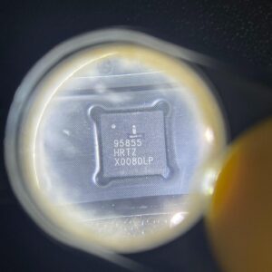
ISL95855HRTZ-T
IMVP8 3+2+1 phase buck controller, R3 technology, 4.5-25V input, 48-TQFN
Brand: Renesas
Package: 48-TQFN (6×6 mm, exposed pad)
IN STOCK: 2156pcs
Cargo cycle: 3-7 Days
The minimum order is 1
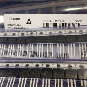
IRFB4019PBF
150V N-Channel HEXFET Power MOSFET, 47A, 34 mΩ RDS(on), TO-220AB
Brand: infineon
Package: TO-220AB
IN STOCK: 2409pcs
Cargo cycle: 3-7 Days
The minimum order is 1
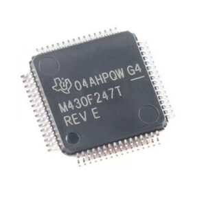
MSP430F247TPMR
TI MSP430 MCU, 16-bit RISC, 92KB Flash, 8KB RAM, 16MHz, LQFP-64
Brand: texas-instruments
Package: See datasheet
IN STOCK: 13371pcs
Cargo cycle: 3-7 Days
The minimum order is 1
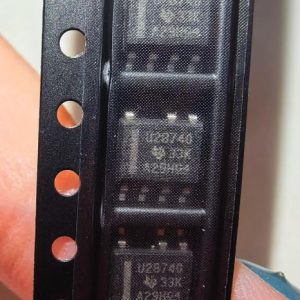
UCC28740DR
CVCC Flyback Controller, 700V startup, opto feedback, <10mW no-load, SOIC-7
Brand: TI
Package: SOIC-7 (4.9 x 3.9 x 1.75 mm)
IN STOCK: 4840pcs
Cargo cycle: 3-7 Days
The minimum order is 1
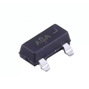
MMUN2211LT1G
NPN digital transistor, R1=10kΩ R2=10kΩ, 50V, 100mA, SOT-23-3, pre-biased BRT switch
Brand: Onsemi
Package: SOT-23-3 (TO-236, SC-59)
IN STOCK: 8500pcs
Cargo cycle: 3-7 Days
The minimum order is 1
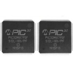
PIC32MX795F512L-80I/PF
32-bit PIC32MX MCU with Ethernet/CAN/USB, 80MHz, 512KB Flash, TQFP-100, industrial
Brand: MICROCHIP
Package: TQFP-100 (14 x 14 mm)
IN STOCK: 7912pcs
Cargo cycle: 3-7 Days
The minimum order is 1