
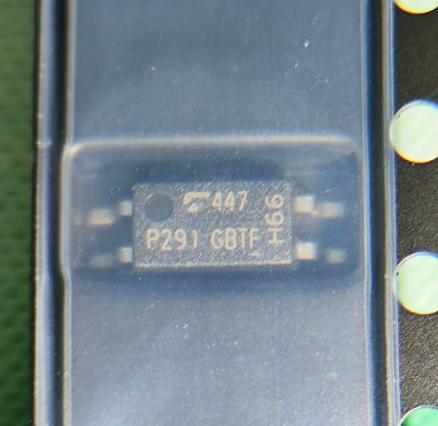
The TLP291GB-TP.SE from Toshiba is a single-channel phototransistor output optocoupler in a compact SOP-4 (SO4) package (2.6 x 7.0 x 2.1 mm). It consists of a gallium arsenide infrared emitting diode optically coupled to a phototransistor, providing 3750 Vrms minimum isolation voltage. The GB rank specifies a current transfer ratio (CTR) of 100% to 400% at IF=5mA, VCE=5V. Key specifications: collector-emitter voltage 80V, forward current 50mA, collector current 50mA, VCE(sat) 0.3V max, reverse voltage 5V, total power dissipation 200mW. Switching characteristics: typical rise time 2-4us, fall time 3-7us. Operating temperature: -55 to 110C. Safety approvals: UL 1577, cUL, EN 60747-5-5 (VDE), EN IEC 62368-1 (VDE), GB 4943.1-2022 (CQC). Creepage/clearance: 5.0mm minimum. The TP suffix denotes tape and reel packaging (2500 units/reel), SE suffix denotes enhanced version. Status: Not Recommended for New Designs (Toshiba recommends TLP291(SE or TLP293 as replacements). RoHS compliant.
Home » Optocouplers / Photocouplers, Optoelectronic Devices » TLP291GB-TP.SE
TLP291GB-TP.SE
1-ch phototransistor optocoupler, CTR 100-400% (GB rank), 3750Vrms isolation, SOP-4, -55~110C, NRND
Effective Inventory
Manufacturer Part:
TLP291GB-TP.SE
Package:
SOP-4 / SO4 (2.6 x 7.0 x 2.1 mm), 11-3C1
Brand:
Product Categories:
Quality Commitment
Shipping & Payment
Service & Packaging
Product Manual
Other recommendations you may be interested in.
Description
Product Introduction: TLP291GB-TP.SE Product Introduction
The TLP291GB-TP.SE from Toshiba is a single-channel phototransistor output optocoupler housed in an ultra-thin SOP-4 (SO4) package measuring just 2.6 x 7.0 x 2.1 mm. The device consists of a gallium arsenide (GaAs) infrared emitting diode (IRED) optically coupled to a silicon NPN phototransistor, providing galvanic isolation between input and output circuits.
The GB rank designation specifies a current transfer ratio (CTR) range of 100% to 400% at IF=5mA and VCE=5V at 25C, meaning the phototransistor collector current equals 1x to 4x the LED forward current. This relatively high CTR range makes the GB rank suitable for low-current drive applications where the input LED current budget is limited, such as microcontroller GPIO-driven isolation circuits.
Key electrical specifications include: collector-emitter breakdown voltage (VCEO) of 80V minimum, forward current rating of 50mA maximum, collector current rating of 50mA maximum, collector-emitter saturation voltage (VCE(sat)) of 0.3V maximum at IC=2.4mA, IF=8mA, and total package power dissipation of 200mW. The input LED forward voltage is typically 1.25V at IF=5mA, with a maximum reverse voltage rating of 5V.
The device provides 3750 Vrms minimum isolation voltage (tested for 1 minute), making it suitable for reinforced insulation applications in power supplies, programmable logic controllers (PLCs), and communication interfaces. The creepage distance and clearance are both 5.0mm minimum, with insulation thickness of 0.4mm minimum, meeting the construction requirements for safety-certified optocouplers.
Switching characteristics include typical rise time of 2us and fall time of 3us (at VCC=10V, IC=2mA, RL=100 ohm), with turn-on time of 3us and turn-off time of 3us typical. These moderate switching speeds make the device suitable for signal isolation rather than high-speed data communication.
The TLP291GB-TP.SE carries comprehensive safety approvals: UL 1577 (File No. E67349), cUL (CSA Component Acceptance Service No. 5A), EN 60747-5-5 (VDE), EN IEC 62368-1 (VDE), and GB 4943.1-2022 (CQC). The VDE option (V4 suffix) provides additional certification with maximum operating insulation voltage of 707 Vpk and highest permissible overvoltage of 6000 Vpk.
The TP suffix indicates tape and reel packaging with 2500 units per reel, suitable for automated SMT assembly. The SE suffix denotes the enhanced version with improved switching characteristics. Note: Toshiba marks the TLP291 as Not Recommended for New Designs and recommends TLP291(SE or TLP293 as replacement products for new designs. The device operates over a wide temperature range of -55C to 110C and is RoHS compliant.
Working Principle: TLP291GB-TP.SE Working Principle
The TLP291GB-TP.SE operates as a phototransistor output optocoupler, converting electrical input signals to optical signals and back to electrical signals to achieve galvanic isolation between circuits.
Input Stage (LED): The input side consists of a gallium arsenide (GaAs) infrared emitting diode (IRED). When forward current (IF) flows through the LED, it emits infrared radiation at a wavelength of approximately 940nm. The forward voltage drop across the LED is typically 1.25V at IF=5mA. The LED must be driven with a current-limiting resistor calculated from the driving voltage: R = (VDRIVE – VF) / IF, where VF is the LED forward voltage. Typical drive currents range from 1mA to 20mA for signal isolation applications.
Optical Coupling: The infrared light from the LED propagates across a transparent dielectric insulation layer within the package. This insulation layer provides the galvanic isolation barrier with a minimum thickness of 0.4mm, achieving 3750 Vrms isolation voltage. The optical coupling efficiency between the LED and phototransistor determines the current transfer ratio (CTR). For the GB rank, the CTR ranges from 100% to 400% at the specified test conditions, meaning IC = CTR x IF.
Output Stage (Phototransistor): The output side consists of a silicon NPN phototransistor. When infrared photons from the LED strike the phototransistor base-collector junction, they generate electron-hole pairs (photocurrent) in the base region. This photocurrent acts as the base drive for the NPN transistor, causing a larger collector current to flow. The phototransistor provides both photodetection and current amplification in a single device, which is why CTR can exceed 100% — the phototransistor current gain (hFE) amplifies the initial photocurrent.
CTR Behavior: The CTR is not constant and varies with: (1) Forward current IF — CTR typically peaks at IF=5-10mA and decreases at both lower and higher currents; (2) Temperature — CTR decreases at temperatures above 25C due to reduced LED efficiency and phototransistor gain; (3) Age — CTR degrades over time due to LED output degradation, typically 10-20% over 10 years at rated current. Design margins must account for these variations, especially when using the GB rank 100% minimum CTR.
Switching Behavior: The phototransistor switching speed is limited by its relatively large junction area (needed for high photosensitivity) and charge storage effects. Rise time (tr) and fall time (tf) are typically 2-4us and 3-7us respectively. The turn-off is slower than turn-on because the phototransistor must clear stored base charge without a dedicated base pull-down resistor. For faster switching, a base-emitter resistor can be added, or a faster optocoupler architecture (e.g., photodiode + amplifier) should be selected.
Isolation: The galvanic isolation is achieved by the physical separation between the LED and phototransistor chips, with only optical coupling bridging the gap. The isolation barrier withstands 3750 Vrms for 1 minute and provides continuous isolation at working voltages up to the rated insulation voltage. The parasitic capacitance across the isolation barrier (typically 0.5-1pF) limits common-mode transient immunity, while the isolation resistance exceeds 10^12 ohms.
Pin Description: TLP291GB-TP.SE Pin Definition and Functions
| Pin | Name | Type | Description |
|---|---|---|---|
| 1 | ANODE | Input | LED anode; connect to positive side of drive circuit through current-limiting resistor; forward current IF up to 50mA; forward voltage VF typically 1.25V at IF=5mA |
| 2 | CATHODE | Input | LED cathode; connect to ground or negative side of drive circuit; reverse voltage must not exceed 5V |
| 3 | EMITTER | Output | Phototransistor emitter; connect to output circuit ground or reference; collector current IC flows from collector (Pin 4) through the load to emitter |
| 4 | COLLECTOR | Output | Phototransistor collector; connect through pull-up resistor to output supply voltage; VCEO maximum 80V; VCE(sat) maximum 0.3V at IC=2.4mA, IF=8mA |
Application Scenarios: In which products and applications is TLP291GB-TP.SE used
| Application | Description |
|---|---|
| Switching Power Supply Feedback | Isolates the secondary-side error amplifier output from the primary-side PWM controller in isolated flyback/forward converters; CTR range 100-400% provides adequate loop gain; 3750Vrms isolation meets safety requirements for mains-powered supplies |
| PLC Digital I/O Isolation | Isolates PLC digital input/output channels from field wiring; wide -55 to 110C temperature range suits industrial environments; VDE and UL approvals meet machinery safety standards |
| Communication Interface Isolation | Provides galvanic isolation for RS-232, RS-485, CAN, and other communication interfaces; prevents ground loops between interconnected equipment; 5mm creepage/clearance meets industrial spacing requirements |
| Microcontroller Signal Isolation | Isolates MCU GPIO signals from high-voltage or noisy circuits; GB rank CTR (100-400%) allows direct MCU pin drive at 5-10mA IF; simple 4-pin interface minimizes component count |
| Gate Drive Signal Isolation | Low-frequency IGBT/MOSFET gate drive isolation for motor drives and inverters; 80V VCEO provides margin for gate drive voltage levels; switching speed suitable for PWM frequencies up to approximately 100kHz |
Alternative Models: What chips are recommended as replacements for TLP291GB-TP.SE
| Model | Manufacturer | Compatibility | Key Difference |
|---|---|---|---|
| TLP291(SE | Toshiba | Recommended Replacement | Same package and pinout; enhanced switching speed; SE version with improved performance; Toshiba recommended replacement for new designs |
| TLP293 | Toshiba | Recommended Replacement | Same package size; different switching speed; Toshiba recommended replacement for new designs; check CTR rank availability |
| PC817C | Sharp/IXYS | Functionally Similar | DIP-4 package (not SOP-4); CTR 200-400% (C rank); 5000Vrms isolation; through-hole mounting; different footprint |
| EL817C | Everlight | Functionally Similar | DIP-4 package; CTR 200-400%; 5000Vrms isolation; industry-standard PC817 compatible; different package type |
| SFH6156-3T | Vishay | Functionally Similar | SOP-4 package; CTR 100-200% (Rank 3); 5300Vrms isolation; similar low-profile design; different CTR range |
Recommend Parts
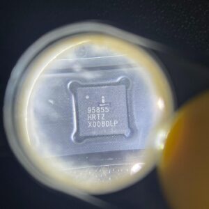
ISL95855HRTZ-T
IMVP8 3+2+1 phase buck controller, R3 technology, 4.5-25V input, 48-TQFN
Brand: Renesas
Package: 48-TQFN (6×6 mm, exposed pad)
IN STOCK: 2156pcs
Cargo cycle: 3-7 Days
The minimum order is 1
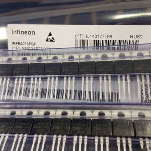
IRFB4019PBF
150V N-Channel HEXFET Power MOSFET, 47A, 34 mΩ RDS(on), TO-220AB
Brand: infineon
Package: TO-220AB
IN STOCK: 2409pcs
Cargo cycle: 3-7 Days
The minimum order is 1
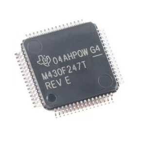
MSP430F247TPMR
TI MSP430 MCU, 16-bit RISC, 92KB Flash, 8KB RAM, 16MHz, LQFP-64
Brand: texas-instruments
Package: See datasheet
IN STOCK: 13371pcs
Cargo cycle: 3-7 Days
The minimum order is 1
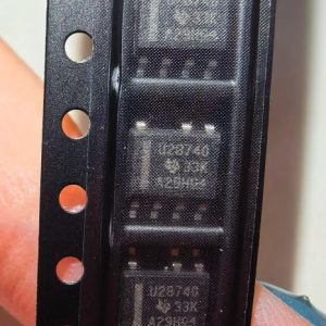
UCC28740DR
CVCC Flyback Controller, 700V startup, opto feedback, <10mW no-load, SOIC-7
Brand: TI
Package: SOIC-7 (4.9 x 3.9 x 1.75 mm)
IN STOCK: 4840pcs
Cargo cycle: 3-7 Days
The minimum order is 1
MMUN2211LT1G
NPN digital transistor, R1=10kΩ R2=10kΩ, 50V, 100mA, SOT-23-3, pre-biased BRT switch
Brand: Onsemi
Package: SOT-23-3 (TO-236, SC-59)
IN STOCK: 8500pcs
Cargo cycle: 3-7 Days
The minimum order is 1
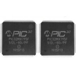
PIC32MX795F512L-80I/PF
32-bit PIC32MX MCU with Ethernet/CAN/USB, 80MHz, 512KB Flash, TQFP-100, industrial
Brand: MICROCHIP
Package: TQFP-100 (14 x 14 mm)
IN STOCK: 7912pcs
Cargo cycle: 3-7 Days
The minimum order is 1