
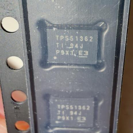
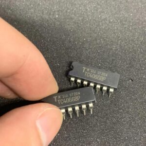
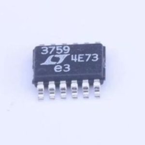
The TPS51362RVER from Texas Instruments is a 3-V to 22-V input, 10-A synchronous step-down converter with integrated MOSFETs in a 28-pin VQFN-CLIP package (4.5×3.5 mm, 0.4-mm pitch). It uses TI’s D-CAP2 control topology for compensation-less operation with POSCAP or all-MLCC output capacitors, fixed 800-kHz switching frequency, and ULQ mode drawing only 100 µA in low-power standby. The output voltage is programmable from 0.6 V to 2.0 V via pin-strapping (1.05/1.2/1.35/1.5 V fixed) or resistor divider. Features include programmable soft start, power good, output discharge, and OCL/OVP/UVP/UVLO/thermal shutdown protection. Targeted at DDR VDDQ/VCCIO rails and POL converters in notebook and embedded systems.
Home » DC-DC Converters, Integrated Circuits ICs » TPS51362RVER
TPS51362RVER
22V 10A sync buck, D-CAP2, 800kHz, 100µA ULQ standby, 0.6-2.0Vout, VQFN-CLIP 28-pin 4.5×3.5mm, -10~85°C
1200
Effective Inventory
Manufacturer Part:
TPS51362RVER
Package:
VQFN-CLIP-28 (RVE) (4.5 x 3.5 x 1.0 mm, 0.4mm pitch)
Brand:
Product Categories:
Quality Commitment
Shipping & Payment
Service & Packaging
Product Manual
Other recommendations you may be interested in.
Description
Product Introduction: TPS51362RVER Product Introduction
The TPS51362RVER is a 10-A integrated-FET synchronous buck converter from Texas Instruments, designed for point-of-load (POL) applications in notebook computers and embedded systems. It operates from a 3-V to 22-V input and produces an adjustable output from 0.6 V to 2.0 V, covering DDR memory VDDQ (1.35 V), VCCIO (1.05 V, 1.2 V), and core logic rails.
The D-CAP2 control topology is the key differentiator. Unlike traditional current-mode or voltage-mode control, D-CAP2 uses adaptive on-time control with internal ripple injection, eliminating the need for Type-II/III compensation components. This simplifies design and supports both POSCAP and all-MLCC output capacitor configurations without stability concerns — a critical advantage in compact designs where MLCCs are preferred for height and reliability.
The ULQ (Ultra-Low Quiescent) mode reduces the bias current to 100 µA when the LP# pin is pulled low, enabling long battery life during system standby. This is a significant improvement over standard auto-skip modes that typically draw 500 µA to 1 mA. In normal PWM mode, the device operates at a fixed 800-kHz frequency, balancing efficiency and inductor size.
The output voltage can be set by pin-strapping REFIN and REFIN2 pins (1.05 V, 1.2 V, 1.35 V, 1.5 V fixed options) without external resistors, or by a resistor divider from the 2.0-V VREF pin for any voltage from 0.6 V to 2.0 V. This flexibility supports multiple DDR generations and rail voltages with a single BOM.
The integrated bootstrap MOSFET switch eliminates the need for an external bootstrap diode. The low-side MOSFET RDS(on) sensing provides temperature-compensated overcurrent protection without an external sense resistor. The VQFN-CLIP-28 package achieves a compact 15.75-mm² footprint with an exposed thermal pad for efficient heat dissipation.
Working Principle: TPS51362RVER Working Principle
**D-CAP2 Control:** The TPS51362 uses TI’s D-CAP2 (Direct Capacitor-Area-Free 2nd generation) control, which combines adaptive on-time modulation with internal ripple injection. The error amplifier compares FB against an internal reference; the on-time generator produces a fixed-duration pulse (proportional to VIN/VOUT) each switching cycle. Internal ripple injection at FB emulates the inductor current ripple, providing the information needed for stable operation without external compensation. This topology is inherently stable with any output capacitor type (POSCAP, MLCC, or mixed) as long as ESR is above a minimum threshold.
**ULQ Mode:** When LP# is pulled low, the device enters ultra-low-quiescent mode. The controller reduces internal bias currents and switches to a pulse-skip mode where the switching frequency scales with load. At zero load, only 100 µA is drawn from the input supply. The output voltage regulation accuracy degrades slightly in ULQ mode but remains within DDR specification limits.
**Power Stage:** The integrated high-side and low-side MOSFETs are optimized for low duty-cycle operation (3-5 V output from 12-19 V input). The low-side RDS(on) is also used for current sensing — the voltage across the low-side FET during the off-time is measured and temperature-compensated to set the overcurrent limit threshold, eliminating an external sense resistor.
**Bootstrap and Pre-Bias:** The integrated bootstrap switch charges the BOOT capacitor from VDD through an internal MOSFET (not a diode), reducing the BOOT voltage drop and enabling start-up into pre-biased outputs without discharging the load first.
Pin Description: TPS51362RVER Pin Definition and Functions
| Pin | Name | Type | Description |
|---|---|---|---|
| 1 | VDD | P | Internal 5V LDO output and internal supply bypass; connect 1µF ceramic to GND; do not load externally |
| 2 | EN | I | Enable; pull high to enable; has internal pull-up; pull below 0.4V to disable; UVLO threshold ~4.5V on VIN |
| 3 | LP# | I | Low-power mode control; pull low for ULQ mode (100µA Iq); pull high for normal PWM/auto-skip; has internal pull-up |
| 4 | PGOOD | O | Open-drain power-good output; asserts when FB is within ±10% of target; connect external pull-up resistor to logic supply |
| 5 | VFB | I | Voltage feedback input; connect to output voltage divider midpoint or tie to VREF for resistor-less fixed voltage; reference 0.6V |
| 6 | VREF | O | 2.0V reference output; 300µA source capability; bypass with 0.1µF to GND; use for resistor-divider output voltage setting |
| 7 | REFIN | I | Output voltage select pin 1; float or tie to GND during startup to select fixed voltage (see truth table); determines 1.05/1.2/1.5/1.35V |
| 8 | REFIN2 | I | Output voltage select pin 2; same function as REFIN; both pins sampled at startup; latched until next power cycle |
| 9 | SS | I/O | Soft-start programming; connect capacitor to GND; 5µA charge current; larger cap = slower start; leave floating for default 1ms |
| 10 | MODE | I | Operation mode select; controls auto-skip vs forced-PWM behavior; tie to GND or float per datasheet recommendation |
| 11-18 | GND | G | Signal and power ground; connect to PCB ground plane and exposed thermal pad; critical for thermal and electrical performance |
| 19 | SW | O | Switch node; connect to output inductor; high dv/dt; keep copper short to reduce EMI; abs max -1.5V to 24V |
| 20 | BOOT | I/O | Bootstrap capacitor; connect 0.1µF ceramic from BOOT to SW; internal bootstrap switch charges from VDD |
| 21 | VIN | P | Main input supply (3-22V); connect input bypass capacitors (10µF ceramic + bulk) close to pin; high-frequency decoupling critical |
| 22-28 | VIN/GND | P/G | Additional VIN and GND pins for power distribution and thermal relief; follow PCB layout guidelines per datasheet |
Application Scenarios: In which products and applications is TPS51362RVER used
| Application | Description |
|---|---|
| Notebook DDR VDDQ Supply | Generate 1.35V DDR3L VDDQ from 5V or 12V system rail; 10A supports 2-DIMM configurations; REFIN/REFIN2 pin-strap sets 1.35V without resistors; ULQ mode maintains standby regulation at 100µA Iq for S3 sleep state; D-CAP2 stable with MLCC-only output |
| Embedded SoC Core Rail | Power 0.8-1.2V core from 5V or 12V intermediate rail; 10A supports mid-range SoCs and FPGAs; resistor divider from VREF sets precise voltage; soft-start controls inrush; PGOOD drives reset logic |
| SSD Controller Power | Convert 5V or 12V to 1.2V core and 1.8V I/O rails; compact VQFN-CLIP footprint fits M.2 SSD form factor; D-CAP2 eliminates compensation components reducing BOM; 100µA ULQ extends laptop battery during idle |
Alternative Models: What chips are recommended as replacements for TPS51362RVER
| Model | Manufacturer | Compatibility | Key Difference |
|---|---|---|---|
| TPS51363RVER | TI | Pin-Compatible Upgrade | Same VQFN-CLIP-28; 12A output (vs 10A); same D-CAP2 control; higher current capability for next-gen platforms |
| TPS51362ARVER | TI | Pin-Compatible, Newer | A-version with improved jitter and EMI performance; same pinout and electrical specs; recommended for new designs |
| ISL95813HRTZ | Renesas | Functional Equivalent | 5-25V input; 10A; D-CAP-like R3 modulation; QFN-28 (5x6mm, larger); similar features; use as second source |
| MP8867GN-Z | MPS | Competitive Alternative | 4.5-22V input; 8A; 800kHz; QFN-20 (3x4mm, smaller); lower current but smaller package; use for space-constrained sub-10A designs |
Recommend Parts
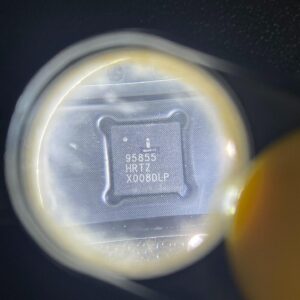
ISL95855HRTZ-T
IMVP8 3+2+1 phase buck controller, R3 technology, 4.5-25V input, 48-TQFN
Brand: Renesas
Package: 48-TQFN (6×6 mm, exposed pad)
IN STOCK: 2156pcs
Cargo cycle: 3-7 Days
The minimum order is 1
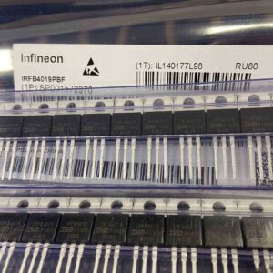
IRFB4019PBF
150V N-Channel HEXFET Power MOSFET, 47A, 34 mΩ RDS(on), TO-220AB
Brand: infineon
Package: TO-220AB
IN STOCK: 2409pcs
Cargo cycle: 3-7 Days
The minimum order is 1
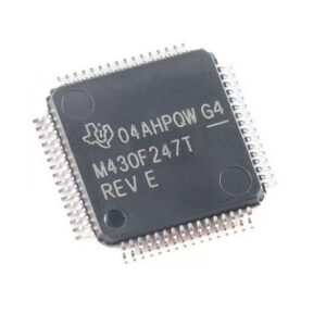
MSP430F247TPMR
TI MSP430 MCU, 16-bit RISC, 92KB Flash, 8KB RAM, 16MHz, LQFP-64
Brand: texas-instruments
Package: See datasheet
IN STOCK: 13371pcs
Cargo cycle: 3-7 Days
The minimum order is 1
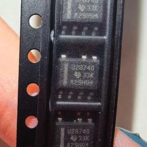
UCC28740DR
CVCC Flyback Controller, 700V startup, opto feedback, <10mW no-load, SOIC-7
Brand: TI
Package: SOIC-7 (4.9 x 3.9 x 1.75 mm)
IN STOCK: 4840pcs
Cargo cycle: 3-7 Days
The minimum order is 1
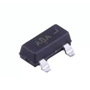
MMUN2211LT1G
NPN digital transistor, R1=10kΩ R2=10kΩ, 50V, 100mA, SOT-23-3, pre-biased BRT switch
Brand: Onsemi
Package: SOT-23-3 (TO-236, SC-59)
IN STOCK: 8500pcs
Cargo cycle: 3-7 Days
The minimum order is 1
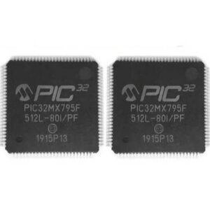
PIC32MX795F512L-80I/PF
32-bit PIC32MX MCU with Ethernet/CAN/USB, 80MHz, 512KB Flash, TQFP-100, industrial
Brand: MICROCHIP
Package: TQFP-100 (14 x 14 mm)
IN STOCK: 7912pcs
Cargo cycle: 3-7 Days
The minimum order is 1